Reciprocating Compressor M Series
5-38
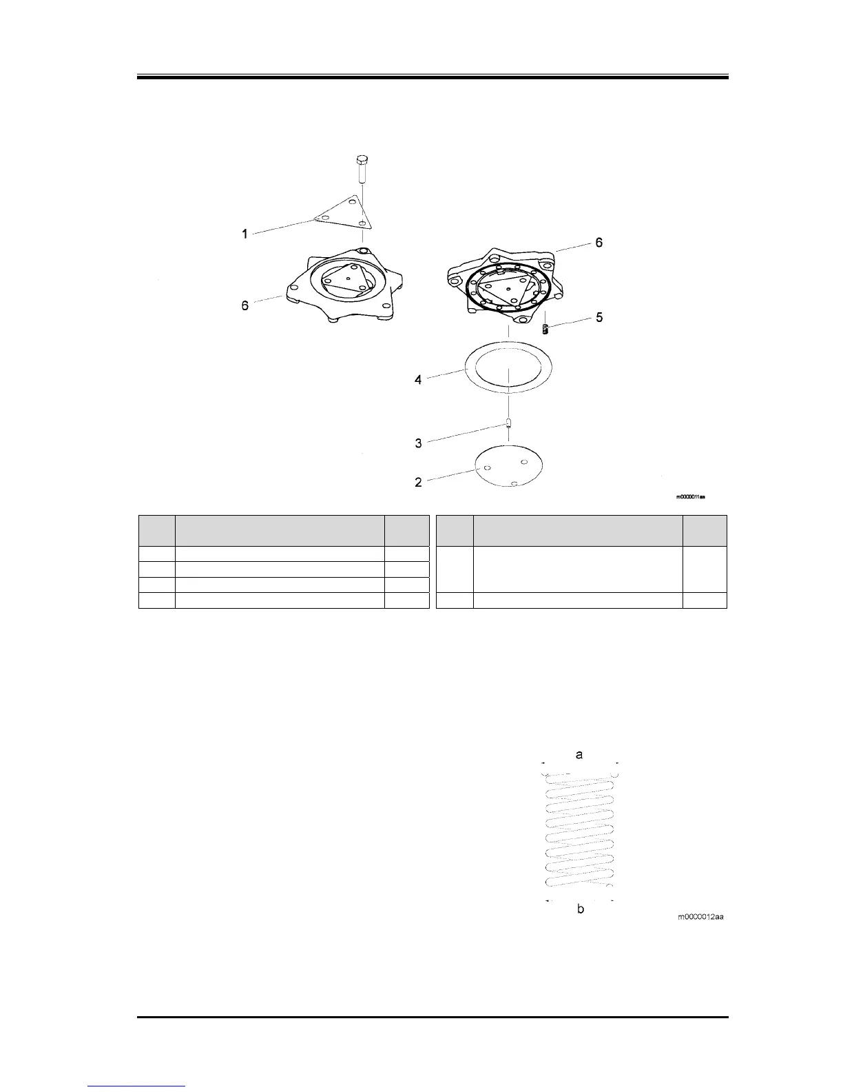
5.5.10 Discharge Valve Cage Assembly
Steps Description
Part
No.
Steps Description
Part
No.
1
Retainer, discharge valve seal bolt
112-2 5
Spring, discharge valve
116
2
Discharge valve seat
111
(Refer to "Assembly of the Discharge
Valve Spring".)
3
Parallel pin, discharge valve sheet
115
4
Discharge plate valve
110 6
Discharge valve cage
109
1. Smooth the discharge valve sheet screw baffle.
2. Remove the parts in the order shown in the diagram.
3. Attach the parts in the reverse order of removal.
4. Bend the discharge valve retainer tabs (1).
5.5.10.1 Assembly of the Discharge Valve Spring
1. Attach the end of the discharge valve spring with
a larger diameter (a) to the discharge valve cage.