Petrol Engines Engine
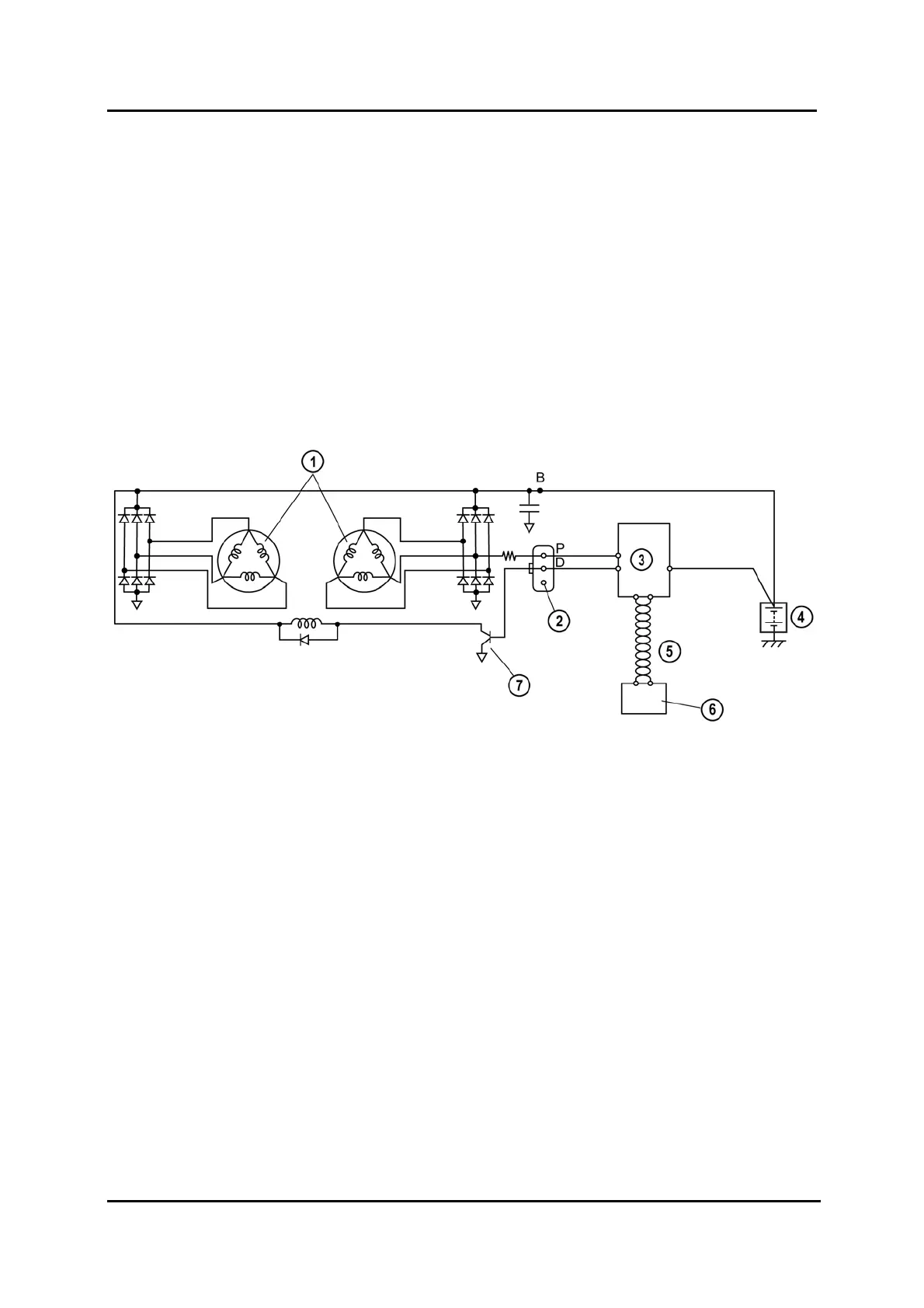
Generator Electrical Diagram
• Two delta connection type stator coils have been introduced. Due to this, the generator
operation noise (electrical noise) is reduced and pulsation occurring through voltage
rectifying in the stator coil is minimized, as a result, stable voltage output is supplied.
• The generator warning light in the instrument cluster illuminates under the following
conditions:
– Charging system voltage low input
– Charging system voltage high input
– IAT sensor circuit low input
– IAT sensor circuit high input
M6FL_01008
1 Stator coil 5 CAN (Controller Area Network)
2 Terminal not used 6 Instrument cluster (warning light)
3 PCM 7 Power transistor
4 Battery
01-8 Service Training Mazda6 Facelift