5. System Description and Operating: Solvent Reservoir and Sampling Flask
Page 5–4 Operating Manual MB-SPS-Systems
©
GmbH – Version 4.3 – 06/2010
5.2. Solvent Reservoir
This chapter describes the installation and exchange procedures for the Solvent Reservoirs.
Refilling and exchanging the Solvent Reservoir is the same procedure.
5.2.1 Prerequisites
> All instructions given in previous chapters have been observed
> All media connections have been made.
Refer to chapter 3 – Installation – for further information
> All valves are closed (position „closed“) – within the safety cabinet as well as for the dispensing
line(s) on the front side of the system.
> The piping and all connections have been checked for leak tightness.
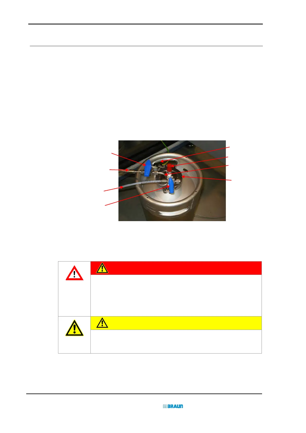
5.2.2 Connections of the Solvent Reservoir
(valve (2) – refer to chapter
4.2)
Metal encased flexible hose.
Connection to the solvent
purification column
Gas supply hose
3 way valve for gas
(valve
(1)–
refer to chapter 4.2)
Over pressure-relief safety valve
Dip tube
Retaining Clip
► During the initial installation all connections have to be made according to the picture above.
Refer to step 5 – 8 in the instructions of chapter 5.2.3.1.
DANGER
The filling of a solvent purification column is specific for each solvent. The
solvent reservoir has to be connected to the designated solvent
purification column. The components of a dispense line are colour coded.
A wrong connection or a wrong filling of the solvent purification column
can lead to uncontrolled chemical reactions.
CAUTION
For safety instructions please refer also to chapter 2 of this manual.
 Loading...