99
SR460/620
SR820
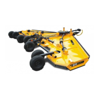
5.6.3.8 Check to see that the hydraulic cylinder
destined to be removed is not under pressure.
There should be some slight movement in the
ram by moving the ram by hand. If no
movement can be made; the system may still
be under pressure.
DANGER! Do not allow anyone or any part
of your body to be underneath the implement
wing.
SR460/620
SR820
5.6.3.9 Lock the positioning of the axle by the means
of using the height stop to double enforce the
supported machine as shown in Figure 5.68.
On SR460/620 machines, raise the machine to a
position which aligns the hole and fit the pin and lynch
pin; see Figure 5.68.
On SR820 machines, lower the machine onto the
minimum height stop by adjusting Figure 5.68(B) and
ensure that it is secured with the nut; see Figure
5.68(A)
SR460/620
SR820
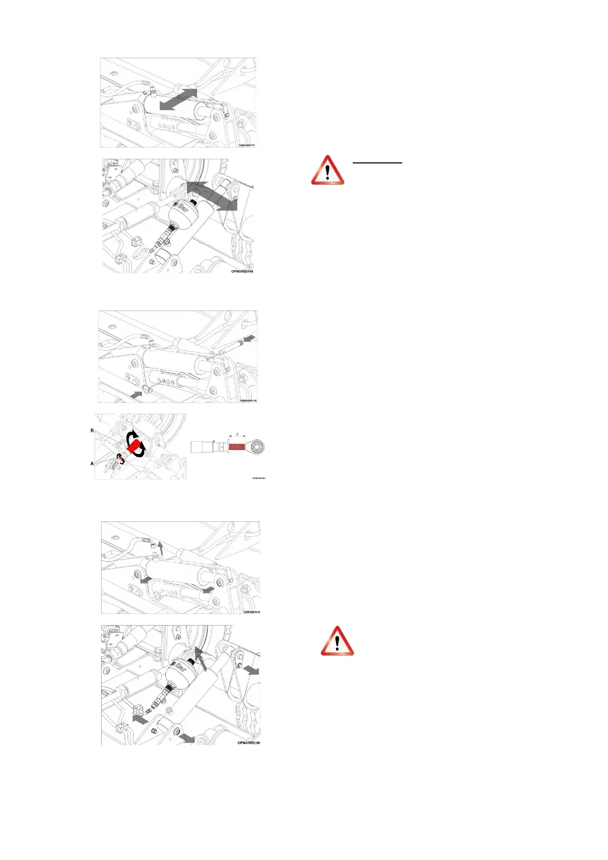
Figure 5.69
5.6.3.10 If no pressure in the ram is sure, slowly
loosen the hydraulic hose connections to
the ram cylinder.
On SR820 machines and SR460/620
machines fitted with an optional Hydragas
float kit support the accumulator bottle
firmly; Figure 5.69
CAUTION! Do not loosen the hydraulic
connections to the cylinder until all pressure
has been relieved from the system.
5.6.3.11 Ensuring that the hydraulic ram can move
and that the machine is supported
substantially so it will not in reaction move,
remove the cylinder pear pins from each of
end of the ram. The cylinder may be heavy,
use proper lifting techniques to lift and
handle the cylinder and if needed get
assistance in lifting from another person