39
a hydraulic hoses and leave quick coupler end exposed. Utilise the coloured plastic caps supplied on the hoses
to keep them contaminant free. Ensure that the tractors hose ports are capped or clean before connecting the
hydraulic hoses from the machine.
The electrical connections between the lights on the machine and the tractor should also be kept clean to ensure
a reliable connection and reduce corrosion.
SR460/620 SR820 All Machines
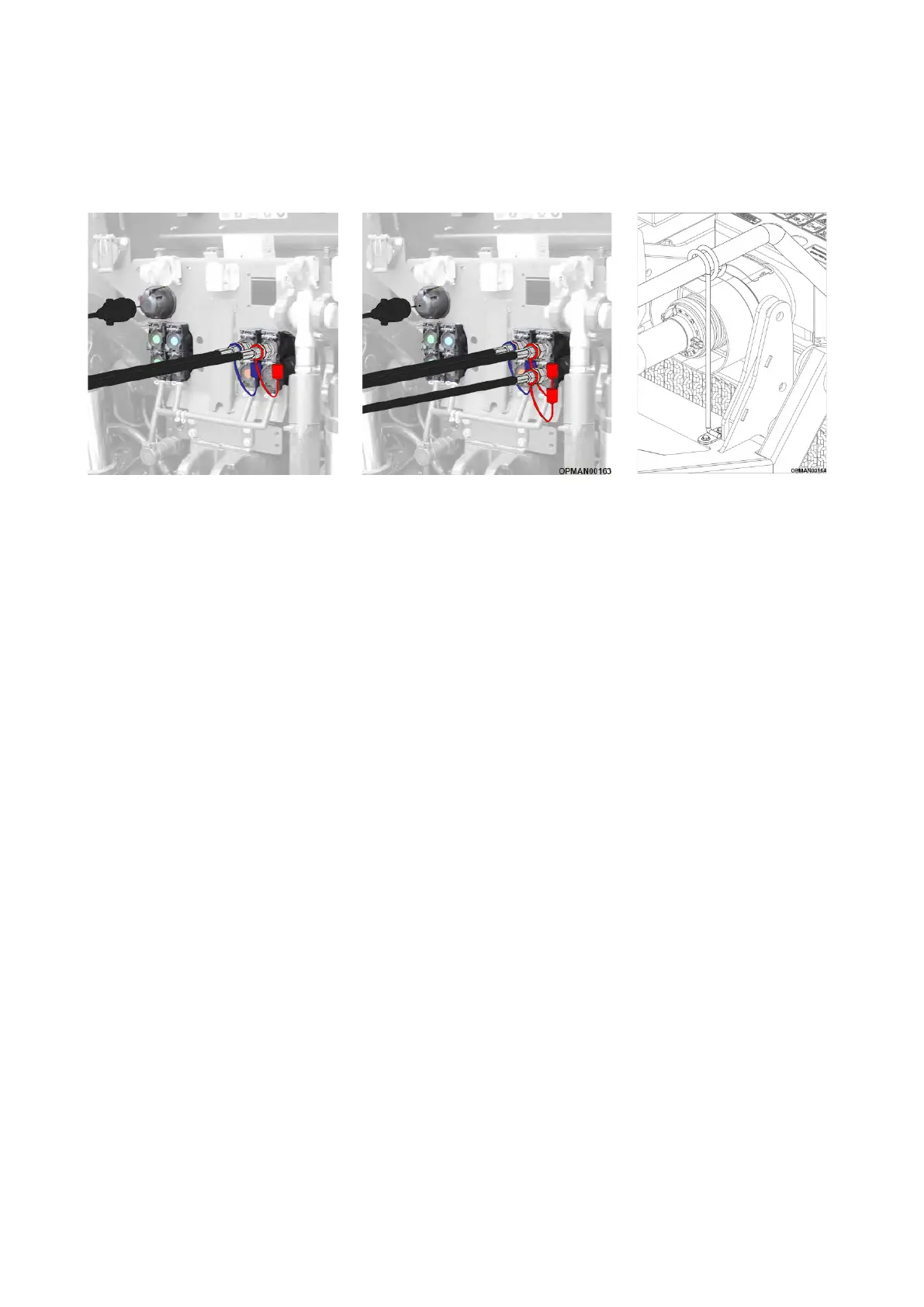
Figure 4.3 – SR460/620/820 Hose & Light Connections Figure 4.4
– SR460/620/820
Ensuring that the quick couplers are clean; proceed to fit the hydraulic hoses. On all SR460/620/820 machines
for visual reference red hose cover caps relate to the wing lifting rams and blue hoses cover caps relate to
the centre lift ram(s). Under the preference of the operator and which service they wish to use on the tractor, fit
the wing lift ram hose into one bank of services on the tractor and the centre lift hose into another; see Figure
4.3. SR820 machines feature two red hoses due to the wing hydraulic rams being double acting; see Figure 4.3.
It is not critical as to which service the hose is fitted to as long as it’s from the same bank. Swapping the hoses
over will cause the action in the tractor to be mirrored opposite; it is down to the preference of the operator in
how they wish to operate the controls in the tractor. For all machines it is important to ensure that the hydraulic
hoses are positively seated into the tractor.
Finally fit and fully seat the 7-pin machine electrical plug into the tractors socket.
IMPORTANT: Ensure that all the hydraulic hoses and the lighting cable are collated together and placed through
the hydraulic hose guide on the machine; see Figure 4.4. This is to ensure that they do not touch the PTO shaft,
bind when turning or get pinched/kinked in use.
For guidance as to the layout of the hydraulic hoses, see the full hydraulic hosing diagrams found in Section
5.6.5. It is important to state that SR460/620/820 wing rams are not independent and not able to be controlled
independently.
With relation to Figure 4.3, there may be some variances in the layout of all of these items depending on the
tractor manufacturer. Figure 4.3 is for visual reference only. Ensure that the operator fully understands the
operations of the tractor before proceeding to use the machine by fully reading the tractor manufacturers
operator manual.
Before proceeding to take the machine onto the road, ensure that all lights work correctly and are orientated
correctly for road transportation (applicable to standard SR460; see Section 4.12.2).