80-0420-23 POWER TONG
Manual № TM12012
Section 8
Page 8.3
©2008-2017 McCoy Global
Torque Measurement
8.0 BASIC TORQUE MEASUREMENT
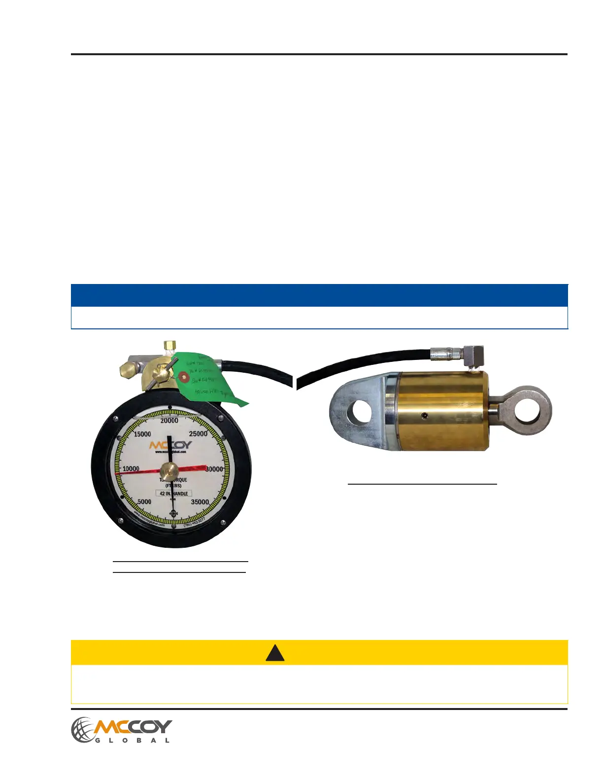
Basic torque measurements are performed using a simple hydraulic measurement system. A hydraulic load cell connects
to a calibrated torque gauge through a reinforced flexible hydraulic hose. The torque gauge is factory-calibrated to display
accurate torque measurements for a tong or tong and backup assembly with a particular arm length. The arm length is
a measurement from the centre of the pipe or casing to the centre of the force being applied to the load cell.
Two load cell options are available. A tension load cell is typically used with a suspended stand-alone tong. This
application requires that the load cell be attached to the rear of the tong as part of the restraint line that opposes the
force generated when the tong makes up or breaks out a joint. A compression load cell is used in a tong and backup
assembly, and is typically located on the rear of the backup between the backup and a stationary frame. The load cell
must be located in the centre of the compression force vector generated between the backup and the frame.
Hydraulic force generated by a load cell is transmitted to the torque gauge via a reinforced flexible hydraulic line. The
hydraulic force is displayed as torque in units of Ft.-Lbs. The torque gauge has a red “peak torque” indicator that tracks
with the torque gauge needle to the point of highest torque, and remains at the point of highest torque until manually
reset. Note that every model of tong and tong and backup assembly has a unique arm length, and the torque gauge must
be calibrated for that arm length. Torque gauges that are not calibrated for the arm length of the tool in service will not
display correct torque. To ensure correct torque measurement, ensure the arm length or “handle” as displayed on your
torque gauge matches the arm length of the tool in service as listed on the specifications page of the technical manual.
The images on this page are for illustration purposes only and may not accurately represent the torque gauge and load
cell that have been supplied with your equipment.
Illustration 8.0.1: Torque Gauge
(For Illustration Purposes Only)
Illustration 8.0.2: Tension Load Cell
Torque gauges and load cells are supplied as a matched calibrated pair. Substituting one or the other will render the
calibration inaccurate even if the actual model numbers appear to be identical. The serial numbers of matching load cell
and torque gauges are clearly identified on the calibration certificate. Should you suspect the accuracy of your torque
measurements, or wish to replace either component the pair should be returned to the factory for re-calibration before
placing into service.
NOTICE
THE IMAGES DISPLAYED ARE SUPPLIED FOR ILLUSTRATION PURPOSES ONLY.
!
CAUTION
TORQUE GAUGES AND LOAD CELLS ARE FACTORY-SUPPLIED SUPPLIED AS MATCHED CALIBRATED
PAIRS. IF REPLACING EITHER COMPONENT THE LOAD CELL AND TORQUE GAUGE MUST BE
RETURNED TO THE FACTORY FOR RE-CALIBRATION BEFORE PLACED INTO SERVICE.



 To Next Page