80-0420-23 POWER TONG
Manual № TM12012
Section 3
Page 3.19
©2008-2017 McCoy Global
Installation & Commissioning
3.5.3 Load Cell Configuration
The tension load cell, coupled to the backup assembly and the frame weldment using shackles, provides the
hydraulic signal to the calibrated torque indicator. The load cell attaches to the backup body and the frame
weldment using shackles. A “breakout chain”, used for arresting motion of the backup when breaking out a
connection, connects the opposite side of the backup body to the frame weldment.
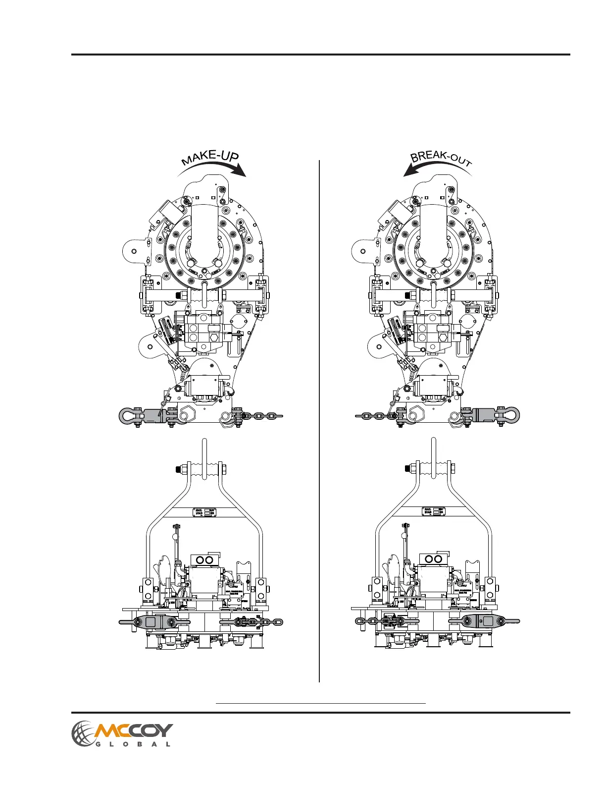
Reference the illustration below for how to correctly configure the load cell for make-up and break-out operations.
Illustration 3.5.3: HD9625 Load Cell Conguration
Load cell & snub line configured
for make-up operations
Load cell & snub line configured
for break-out operations