5
General Notes and Connector Information
1. It is recommended that a qualified professional assist you in
the choice and installation of a McIntosh Theater System for
your home.
2. Before making any connections to the MHT200, make sure
that the Main POWER Switch is in the Off position. When
the MHT200 and other McIntosh Components are in their
Standby Mode the Microprocessor’s Circuitry inside each
component is active and communication is occurring
between them. Failure to do so could result in
malfunctioning of some or all of the system’s normal
operations.
3. The optional McIntosh TM1 AM/FM Tuner Module can be
added to the MHT200 A/V System Controller. The TM1 is
available from your McIntosh Dealer and can be installed at
any time, usually while you wait. Refer to page 58 for
additional information on the TM1.
4. Connecting Cables and Connectors are available from the
McIntosh Parts Department:
Data and Power Control Cable Part No. 170-202
Six foot, shielded 2 conductor, with a 1/8 inch stereo mini
phone plug on each end.
5. For additional connection information, refer to the owner’s
manual(s) for any component(s) connected to the MHT200
A/V System Controller.
6. System Setup operations must be performed in the order they
appear in the Main System Setup Menu as they are
interactive.
7. The Zone A and Zone B IR Inputs, with 1/8 inch mini phone
jacks, are configured for non-McIntosh IR sensors such as a
Xantech Model 291-10. To avoid possible interaction,
disable the MHT200 Front Panel Sensor using the built-in
switch. The switch is recessed and available through an
opening in the bottom cover. The opening is located behind
and to the right of the Front Panel Sensor.
8. In order to hear bass frequencies below 80Hz, your system
must include either a Subwoofer or Large Front
Loudspeakers.
9. Zone B Audio is analog only, a Digital Audio Input Signal
Source will not appear at the Zone B Audio Outputs. The
source component Analog Outputs must also to be connected
to the MHT200.
10. When an assigned Digital Input and a matching Analog
Input are in use, the MHT200 automatically searches first for
a Digital Signal. If no Digital Signal is sensed, it switches to
the Analog Input.
11. Certain DVD or Laser Video Disc Players that are
reproducing Digital DTS Signals into a MHT200 Digital
Input, may only produce noise from their Analog Outputs at
the same time. If Zone B is turned on and that same input is
selected, that noise will be heard.
12. The MHT200 Input Source Name “DVD” is equivalent to
“V-Aux” on some McIntosh Keypads, Remote Controls and
Audio/Video Control Centers.
Important Information
13. Up to four McIntosh Sensors or Keypads can be wired in
parallel for both Zones A and B.
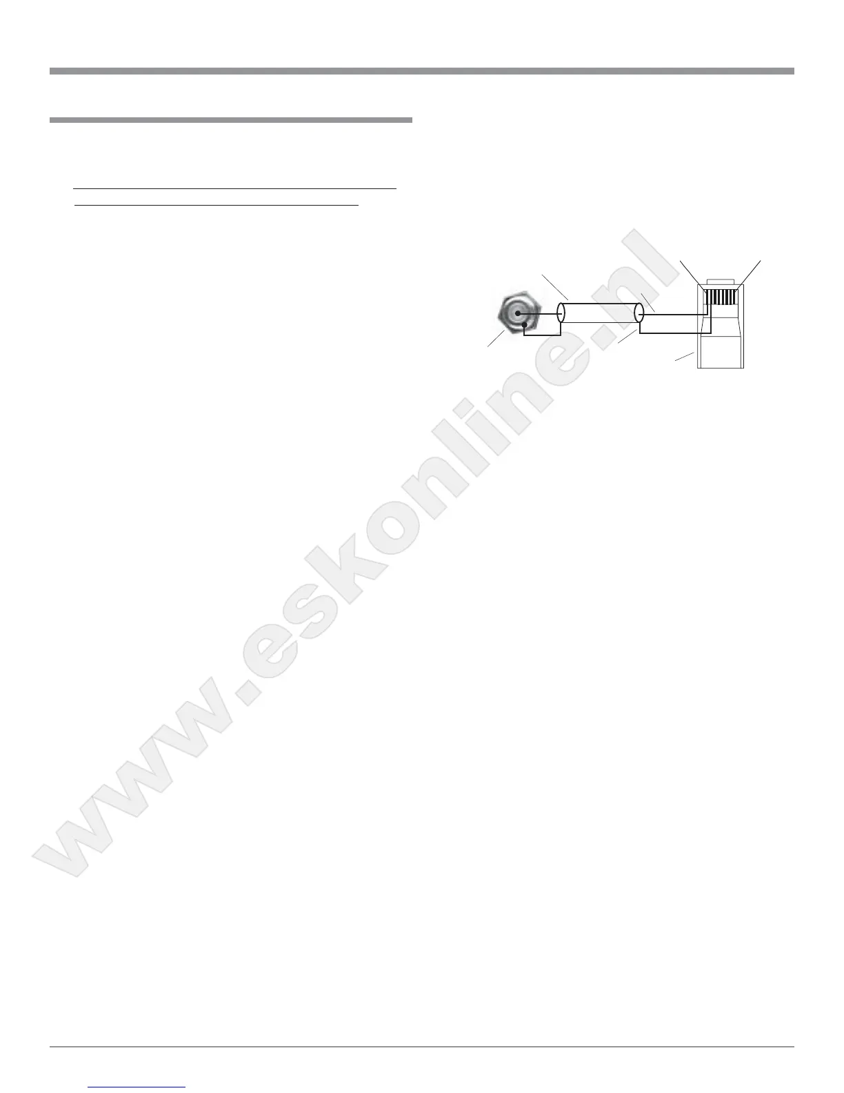
14. When a McIntosh WK-2 Keypad or a R649 Sensor is to be
connected to the McIntosh MHT200 A/V Control Center that
uses a RJ-45 Connector Plug instead of the “F” Coax
Connector, connect the Center Conductor to Pin 1 and the
Shield Conductor to Pin 2. Refer to the illustration below.
15. There are three types of Video Signals that can be connected
to and selected by the MHT200; Composite, S-Video and
Component. Zone A and B, VCR 1 and 2 have both
Composite and S-Video Outputs; the Component Video
Output is for Zone A only.
16. There are four Power Control Jacks on the MHT200 that can
be used to switch on various electronic equipment. The jacks
labeled ZONE A, ZONE B and ACCessory are designed for
McIntosh Components. These three jacks supply a Positive
going twelve volt Turn-On Signal. The jack labeled VIDEO
supplies a twelve volt Turn-On Signal, that can be set for
either Positive or Negative going voltage.
17. The On-Screen Setup Menu and Operational features are
available at the MHT200 MON ZONE A Video Outputs (S-
Video or Composite). There is no On-Screen Information
present at the MHT200 Component Video Output.
19. It is normal to hear a momentary clicking type sound coming
from the muting relays inside the MHT200 when Inputs,
Surround Modes and the Digital Bitstream Signals are
changed.
RJ-45
Plug
Data Ground
(to Pin 2)
Shielded Cable Data Signal
(to Pin 1)
“F” Connector
Pin 8Pin 1
www.eskonline.nl
 Loading...