9
Installation
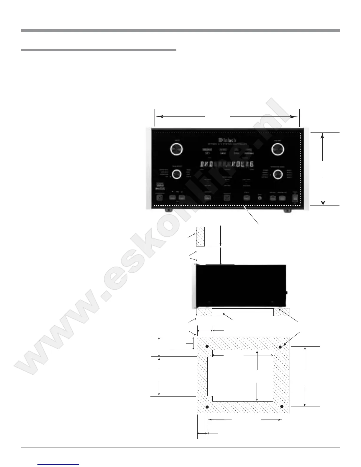
The MHT200 can be placed upright on a table or shelf,
standing on its four feet. It also can be custom installed in a
piece of furniture or cabinet of your choice. The four feet
may be removed from the bottom of the MHT200 when it
is custom installed as outlined below. The four feet to-
gether with the mounting screws should be retained for
possible future use
if the MHT200 is
removed from the
custom installation
and used free stand-
ing. The required
panel cutout, venti-
lation cutout and
unit dimensions are
shown.
Always provide
adequate ventilation
for your MHT200.
Cool operation en-
sures the longest
possible operating
life for any elec-
tronic instrument.
Do not install the
MHT200 directly
above a heat gener-
ating component
such as a high pow-
ered amplifier. If all
the components are
installed in a single
cabinet, a quiet run-
ning ventilation fan
can be a definite as-
set in maintaining
all the system com-
ponents at the
coolest possible op-
erating temperature.
A custom cabinet
installation should
provide the follow-
ing minimum spac-
ing dimensions for
cool operation. Al-
low at least 4 inches
(10.16cm) above the
top, 2 inches
(5.08cm) below the
Installation
8-
5/16
"
21.11cm
17-
1/16
"
43.34cm
MHT200 Front Panel
Custom Cabinet Cutout
Cutout
Opening
for
Ventilation
Cutout Opening for Ventilation
Support
Shelf
Cabinet
Front
Panel
Chassis
Spacers
MHT200 Side View
in Custom Cabinet
MHT200 Bottom View
in Custom Cabinet
7"
17.78cm
14-
1/2
"
36.83cm
15"
38.1cm
14-
1/16
"
35.71cm
2-
1/2
"
6.35cm
Cutout Opening
for
Custom Mounting
6"
15.24cm
Opening
for Ventilation
1"
2.54cm
2"
5.08cm
12-
1/2
"
31.75cm
1-
1/4
"
3.18cm
bottom and 1 inch (2.54cm) on each side of the A/V Sys-
tem Controller, so that airflow is not obstructed. Allow 21
inches (53.34cm) depth behind the front panel. Allow 1
inch (2.54cm) in front of the mounting panel for knob
clearance. Be sure to cut out a ventilation hole in the
mounting shelf according to the dimensions in the drawing.
www.eskonline.nl
 Loading...