44 OM Centrif Micro ΙΙ-5
b) Depending on the top-level selected, a second level of screens will appear. For example,
selecting ALARM will go the next level of menus under ALARM (ALARM LOG or
ACTIVE ALARM). Selecting VIEW will go the next level of menus (VIEW
COMPRESSOR STATUS, VIEW UNIT STATUS, VIEW EVAPORATOR, or VIEW
CONDENSER). Selecting SET will go to a series of menus for looking at and changing
setpoints.
c) After selecting this second level, the desired screen can be acquired using the arrow keys.
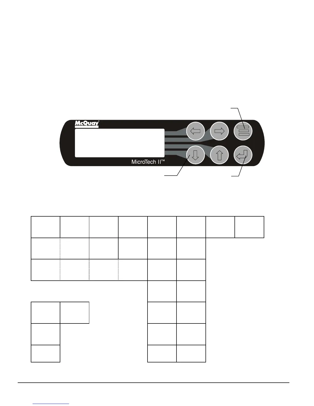
A typical final screen is shown below.
Pressing the MENU key from any menu screen will automatically return you to the MENU mode.
Figure 28, Typical Menu Display and Keypad Layout
Air Conditioning
VIEW UNIT STATUS
Unit = COOL
Compr. #1/#2=OFF/OFF
Evap Pump = RUN
Screen Content
Figure 29, View Screens
VIEW UNIT
STATUS (1)
Unit = COOL
Compressor 1=X
Ev/Cn Pmps= /
VIEW UNIT
Cond
VIEW UNIT
Sat Cond
VIEW UNIT
TOWER(1)
Setpoint=
(1)
Evap LWT = °F
(1)
Evap LWT = °F
VIEW
.
VIEW
Subcooling=
VIEW UNIT
STATUS (2)
Compressor 2=X
Start-Start Tmr=
Inhibit Oil Temp
VIEW UNIT
. In Out Delta
HtRc
Cond XX XX XX
VIEW UNIT
REFRG (2)
Lift Press =
VIEW UNIT
TOWER(2)
VIEW COMP
(2)
Lift Press =
(2)
Lift Press =
VIEW UNIT
WATER . (3)
Water Flo Rates
Evap = XXX
Cond = XXX
(3)
(3)
Net
Alarm Screens
(4)
Feed Temp =
(4)
Feed Temp =
Lift Temp
ACTIVE
Fault
(5) .
Suction °F °F
Dischrg °F °F
(5) .
Suction °F °F
Dischrg °F °F
(6) . .
Psi
°
F
(6) .
Psi
°
F
Sat Cond
(7)
(7)
MENU Key
ENTER Key
ARROW Keys