13
INSTALLATION
4.3 ElectricalConnections
compact piezo LED allows various electrical
congurationstosatisfythecharacteristicsof
the dental unit in which it is housed.
The dental units to which the
compact piezo LED device can be connected
must be able to provide one of the following
power supplies:
• 24V~50/60Hzor
• 32 V
with minimum power 40VA.
Moreover, it must have a 2A, 250V safety fuse.
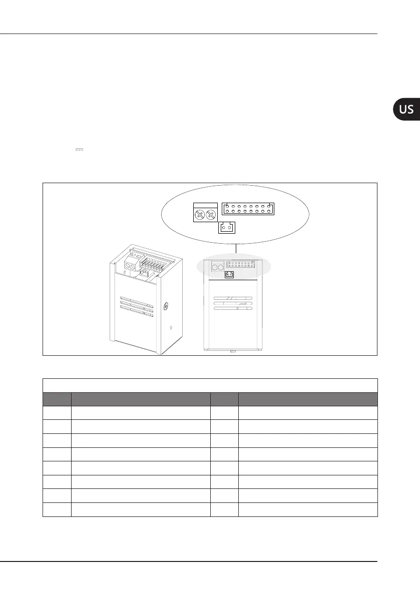
Fortheelectricalconnections,the
compact piezo LED device is equipped with 2
connectors (see
Figure3apagina13
):
• M1 : connector with 2x8 contacts for the
module controls;
• M2 : connector with 2 contacts for
connection of the handpiece cable
(piezoelectricelementscontrol);
• M3 : connector with 2 contacts for
connection of the handpiece cable (LED
control).
M1
M3
M2
M1
M2
1 21 2 3 4 5 6 7 8
16 15 14 13
12
11
10 9
16 15 14
1 2
M3
Figure3 – Module connectors.
M1ConnectorPin-Out
Pin Signal Pin Signal
1 Reserved 9 Bypass capacity
2 RIS 10 GND
3 TX 11 Pedal +
4 RX 12 Power Selection
5 Valve 13 AC In
6 Power Control 14 AC/DCIn
7 Pedal - 15 GND
8 +Vdc 16 Reserved
Table5 – M1 Connector Pin-Out.