18
COMPACT PIEZO LED
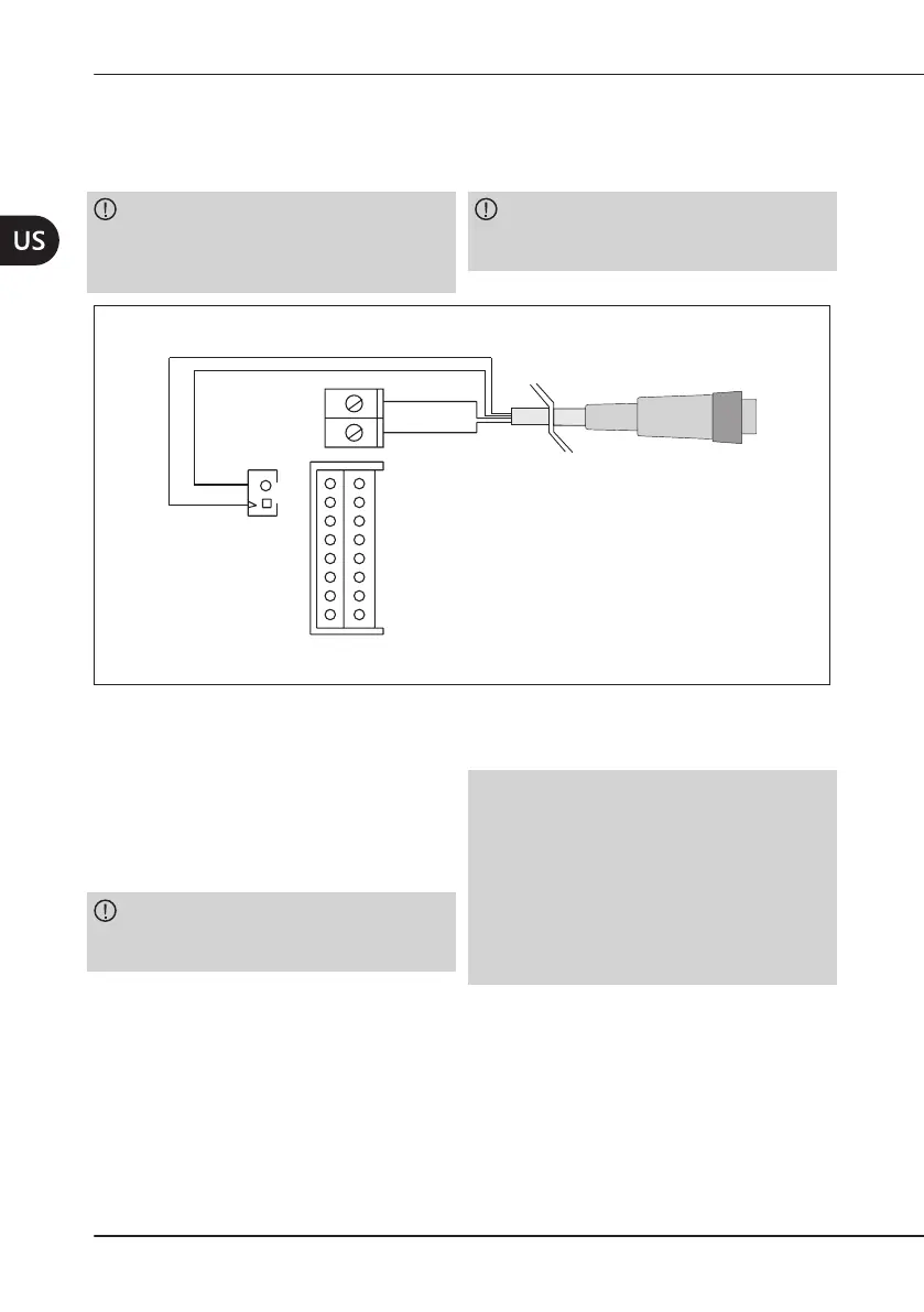
4.3.7 ConnectingtheCordoftheScalerHandpiece
Connect the piezoelectric pilot wires of the cord to the M2 terminal in accordance with the
indicatedpolarity.ConnecttheLEDwires(purpleandgreyofthehandpiececord)toconnector
M3 in accordance with the indicated polarity.
CAUTION: Do not invert the position
on the connector (
Figure4apagina18
)
of the red wire and black wire of the scaler
handpiece cord.
CAUTION: Do not wire the red and black
wires of the scaler handpiece cord together
with other cables.
M3
M2
Grey
Red
Purple
Black
Scaler handpiece cord
Figure4 – Handpiece cord connection.
4.3.8 StandardConnections
To facilitate the installation of
compact piezo LED in the dierent types of
dental units,there are 7 available “standard”
connection layouts, each equipped with a
connectingcabletothedierentdentalunit.
CAUTION: If long connections are
required for the power supply, use wires with
a suitable wire gauge, for example 1.5 mm
2
.
NOTE*: Near the connection on the module
it is advisable to wind the power line 3 times
onaferrite(seefollowingchapters).The
ferriteisnotsuppliedstandard.Followingisa
brief list of the usable models:
• PhilipsCST17/9.5/13-3S4;
• FerroxcubeCST17/9.5/13-3S4;
• Wurth74270091.