17
INSTALLATION
4.3.5 Enabling
Theseconnectionsallowtheactivationoftheoperatingcycle.Fortheseconnectionstoo,there
aredierentcongurationstosuitthedierenttypesofdentalunits.
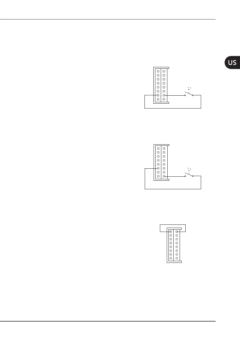
4.3.5.1 EnablingofPedalwithNegativeSignal
The pedal must be connected to pins 10
and7.
1
2
3
4
5
6
7
8
13
16
15
14
12
9
10
11
Pedal
4.3.5.2 EnablingofPedalwithPositiveSignal
The pedal must be connected to pins 8
and 11.
1
2
3
4
5
6
7
8
13
16
15
14
12
9
10
11
Pedal
4.3.6 Other Connections
Pins1and16mustalwaysbeconnected
to each other.
1
2
3
4
5
6
7
8
13
16
15
14
12
9
10
11