19
INSTALLATION
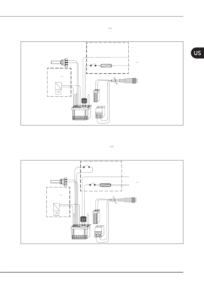
4.3.8.1 LayoutA
Thepowersupply (24V~50/60 Hz±10%or 32V ±10%) andconsentare providedbythe
pedal.
Thepowerisregulatedbya2.2KΩlinearpotentiometer(see
Figure5apagina19
).
9 16
8 7 6 5 4 3 2 1
Fuse holder, fuse and pedal
are not included in the
Mectron supply
Pedal
T 2 A
Fuse
Yellow
Yellow
2,2 KΩ linear
potentiometer
Black
Red
Green
Green
White
White
Solenoid valve
(optional)
24 V
2,5W maximum
Scaler handpiece cord
Power supply
24 V
~
50/60 Hz or
32 V
Minimum 40VA
Ferrite*
Grey
Purple
12
Figure5 – Layout A
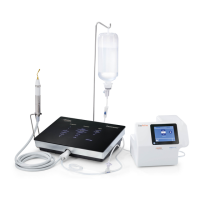
4.3.8.2 LayoutB
The power supply (24 V~ 50/60 Hz ±10% or 32 V ±10%) is provided by contact with the
instrumenttrayandconsentisprovidedbythepedal.Thepowerisregulatedbya2.2KΩlinear
potentiometer (see
Figure6apagina19
).
9 16
8 7 6 5 4 3 2 1
Fuse holder, fuse,
pedal and instrument
tray not included in
the Mectron supply
Instrument tray
T 2 A
Fuse
Yellow
Yellow
2,2 KΩ linear
potentiometer
Black
Red
Green
Green
White
White
Solenoid valve
(optional)
24 V
2,5W maximum
Scaler handpiece cord
Power supply
24 V
~
50/60 Hz or
32 V
Minimum 40VA
Pedal
Blue
Blue
Ferrite*
Grey
Purple
12
Figure6 – Layout B