14
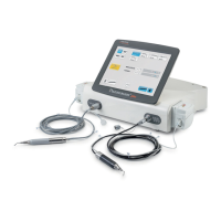
COMPACT PIEZO LED
M2ConnectorPin-Out
Pin Signal
1 Vout handpiece
2 Neutral
Table6 – M2 Connector Pin-Out.
M3ConnectorPin-Out
Pin Signal
1 LED A
2 LED K
Table7 – M3 Connector Pin-Out.
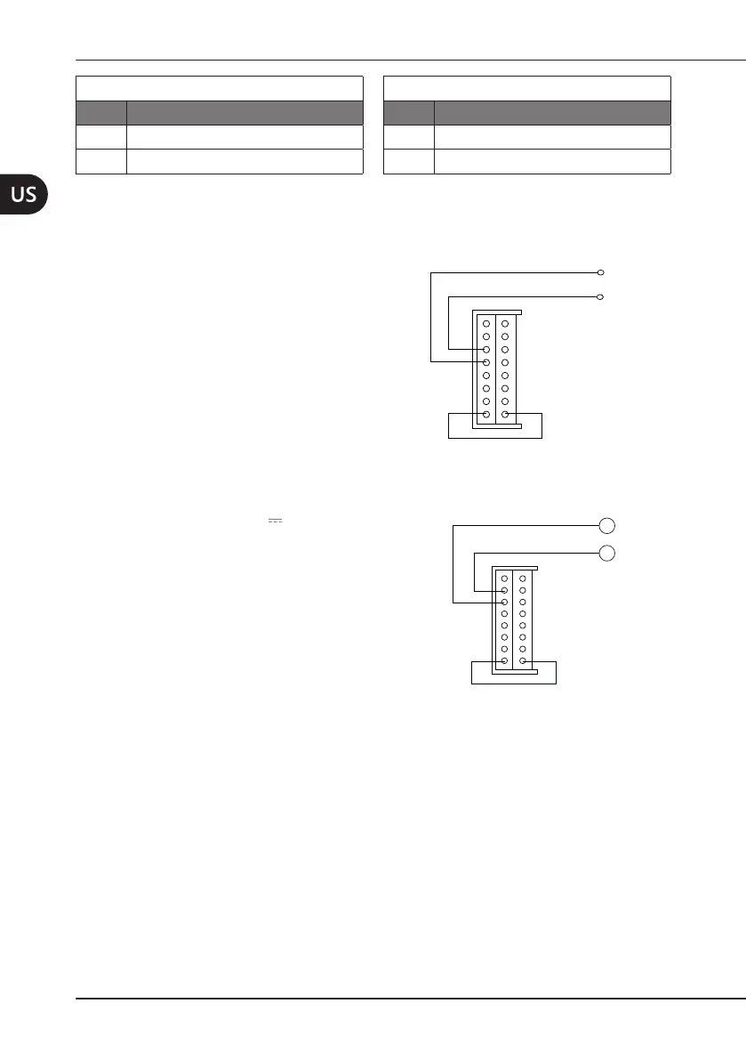
4.3.1 Alternate24VPowerSupply
Topowerthemoduleat24V~50/60Hz
connect pins 13 and 14 (see
Figure 3 a
pagina 13
and Table 5 a pagina 13).
Connect pins 8 and 9 to insert the bypass
capacity present on the board to lter
any disturbances on the power supply.
Observe the voltage and current values
indicated on the plate.
1
2
3
4
5
6
7
8
13
16
15
14
12
9
10
11
~
Vin
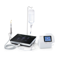
4.3.2 Direct32VPowerSupply
To power the module at 32V connect
the power supply positive on pin 14 and
the negative on pin 15.
Connect pins 8 and 9 to insert the bypass
capacity present on the board to lter
any disturbances on the power supply.
Observe the voltage and current values
indicated on the plate.
1
2
3
4
5
6
7
8
13
16
15
14
12
9
10
11
+
-