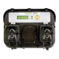
TECHNOPOOL3 INSTALLATION
Dosing systems for swimming pools ENGLISH
ADSP7000716 rev. 1.0 25/01/2017 6/64
2.2.4 Dosing enabling signal (V1)
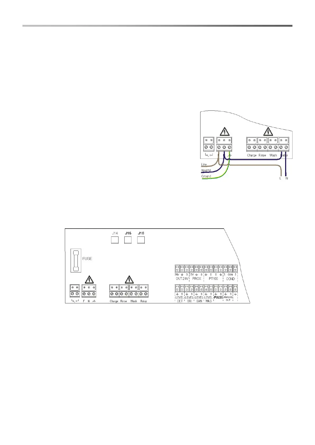
Connect the enablement signal to the dosing (20-230VAC) on input CHARGE.
2.2.5 pH pump product level probe
Connect the level probe (on/off contact, without voltage) to input LEVEL RIN.
2.2.6 Rx pump product level probe
Connect the level probe (on/off contact, without voltage) to input LEVEL SAN.
2.2.7 Alarm output – 24V OUT Clamp
It is an alarm repetition output that provides a voltage at 30VCC with a
maximum absorption of 500mA.
2.2.8 Solenoid valve output – RELAY Clamp
RELAY clamp provides a dry contact (not live) and it is used to control
the solenoid valve.
To have a voltage on the RELAY clamp equal to the power voltage, i.e.
230VAC, follow the diagram indicated on the side.
2.2.9 Pump switches
The system can be set with dose enable switches for each pump, which block the dosing of the associated pump.
Switches are connected to the circuit in the following way:
pH Pump on connector J16
Rx Pump on connector J15