EasyManua.ls Logo

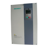
Megmeet MV600L Series User Manual

Megmeet MV600L Series
74 pages
To Next Page IconTo Next Page
Page #1 background imageLoading...
Page #1 background image
1
MV600L Series Drive Special for Lifting
Simple User Manual
Document Version: V1.0
Archive Date: 2015/09/22
BOM Code: R33010233
Shenzhen Megmeet Drive Technology Co., Ltd. provides full technical support for our
customers,customers can contact local Megmeet offices or customer service centers, or
directly contact Megmeet headquarters.
Shenzhen Megmeet Drive Technology Co., Ltd.
All rights reserved. The contents in this document are subject to change without notice.
Shenzhen Megmeet Drive Technology Co., Ltd.
Address: 5th Floor, Block B, Unisplendor Information Harbor, Langshan Rd., Science &
Technology Park, Nanshan District, Shenzhen, 518057, China
Website: www.megmeet-drivetech.com
Tel: +86-755-86600500
Fax: +86-755-86600562
Service email: crane@megmeet.com
Questions and Answers:

Megmeet MV600L Series Specifications

General IconGeneral
ModelMV600L Series
Cooling MethodForced air cooling
Storage Temperature-20°C to +60°C
Control MethodVector control
Protection FeaturesOvercurrent, overvoltage, undervoltage, overheat, short circuit, phase loss
Communication ProtocolModbus RTU
Operating Temperature-10°C to +40°C
Humidity5% to 95% (non-condensing)
AltitudeUp to 1000m

Summary

Foreword

Precautions for Unpacking Inspection

Important safety and handling instructions before using the product.

Chapter 1 Introduction of MV600L Series Drive

Product Model and Specifications

Covers product naming, series, and technical details like electrical and operational features.

Chapter 2 Wiring of Drive

Main and Control Circuit Wiring

Details connections for main power, output terminals, and control signals.

Drive Connection Recommendations

Details recommended fuse capacity and wire cross-section areas.

Basic Operation Wiring

Shows wiring diagrams for connecting the drive for typical operation.

Control Circuit Wiring

Describes the connection of control signal and communication terminals.

Control Terminal Sequence

Illustrates the terminal layout for control connections.

Control Circuit Terminal Details

Details the function and specification of each control circuit terminal.

Encoder Wiring Notes

Provides guidelines for connecting encoder signals (open collector, push-pull, differential).

Chapter 3 Parameter List

System Management and Basic Parameters

Covers system settings, motor parameters, control modes, and speed control configurations.

Encoder, Start/Stop, and Auxiliary Parameters

Details encoder settings, start/stop behavior, and auxiliary functions like jog control.

VF, Digital I/O, and Brake Control Parameters

Covers V/F settings, digital inputs/outputs, and brake control logic.

Analog I/O, Special Lifting, and Protection Parameters

Details analog signals, lifting-specific functions, and protection settings.

Advanced, Multi-Stage, and Slewing Control Parameters

Covers advanced functions, multi-stage references, and slewing operation settings.

Lifting, Brake, and Special Lifting Control Parameters

Parameters for lifting, brake control, and specialized lifting functions.

Protection and Fault Parameters

Comprehensive settings for overload protection, fault types, and detection.

Drive Parameters

Includes serial number, software version, and rated capacity/voltage/current settings.

Chapter 4 Parameter Description

System Management and Motor Parameters

Detailed explanation of system settings, motor configuration, and auto-tuning procedures.

Speed, Start/Stop, and Auxiliary Parameters

Covers speed control, start/stop methods, and auxiliary functions like zero servo and jog.

Multi-Stage Reference, Slewing, Lifting, and Brake Control

Details multi-stage references, application-specific controls (slewing, lifting), and brake management.

Special Lifting Control and Protection Parameters

Advanced lifting functions, overspeed detection, and protection settings.

Chapter 5 Debugging Guide

Application Wiring Diagrams

Wiring diagrams for slewing, luffing, and lifting applications to aid in debugging.

Default Function Code Settings by Mode

Default parameter configurations for various operating modes to assist debugging.

Chapter 6 Troubleshooting

Displaying Exceptions and Solutions

A comprehensive table of fault codes, possible causes, and solutions for diagnosing issues.

Deceleration Over-Voltage Faults

Faults related to deceleration over-voltage and their resolutions.

Inverter Module Over-Temperature

Troubleshooting for inverter module overheating issues.

Abnormal Serial Port Communication

Faults related to serial port communication errors.

Grounding Short Circuit Faults

Faults caused by grounding short circuits.

Abnormal AI Analog Input

Troubleshooting for abnormal analog input signals.

Overspeed and Drive Overload Faults

Identifies causes and solutions for overspeed and drive overload faults.

Operation Exceptions and Solutions

Addresses common operational problems like unresponsive panels and unmodifiable codes.

Drive Fails to Work

Troubleshooting steps when the drive fails to operate after pressing the run key.

-LU- Report on Drive Startup

Diagnosing the "-LU-" report during drive startup with large loads.

Appendix 1 Braking Unit and Resistor

Recommended Braking Resistor Specifications

Specifies recommended braking resistor power and resistance for different drive models.

Appendix 2 LED Display Symbol Identification

LED Display Symbol Meanings

Explains the meaning of various symbols shown on the drive's LED display.

Appendix 3 Warranty and Service

Warranty Terms and After-Sales Support

Outlines product warranty coverage, exclusions, and procedures for service and repairs.

Related product manuals