150 of 289
b. Remove the PCB cover.
5. Remove the lower arm rear cover.
Figure 2 - Z-Motor PCB Connections
6. Disconnect both the z-motor harness and motor and hall sensor leads (marked “Z Motor” and “Z
Hall Enc”).
7. Use a small pair of wire cutters and cut off the cable ties that tie the z-harness to the user inter-
face harness.
8. Pull the z-harness all the way through the cable through-hole to the back of the machine and let
the harness hang off the back of the machine.
Figure 3 - Z-Belt Idler Pulley
9. Slowly loosen the z-belt idler pulley to remove the tension from the z-drive belt.
10. Cut all of the cable ties that tie the x- and z-harness leads together.
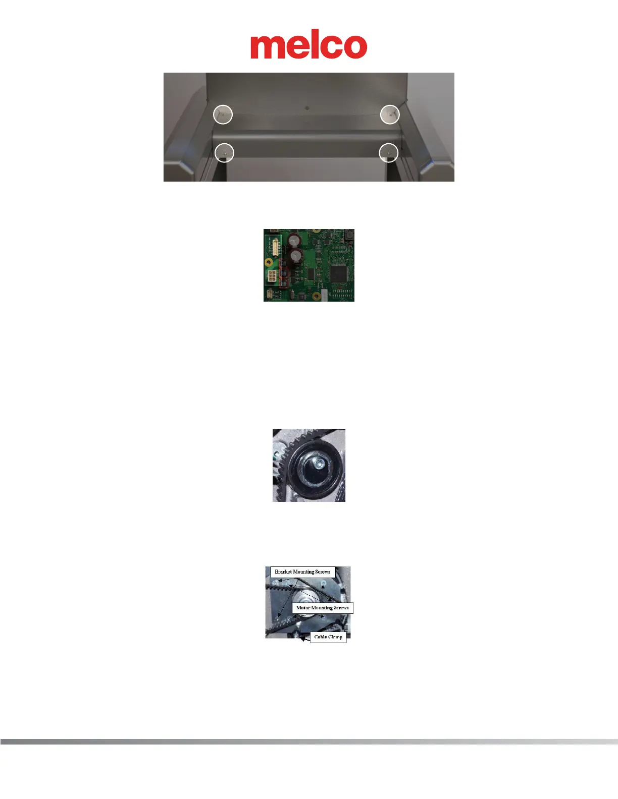
Figure 4 - Z-Motor Mounting Screws
11. Remove the cable clamp located at the bottom of the z-motor mounting bracket.
12. Remove the bracket mounting screws as shown in Figure 4 above.
13. Pull the x-cable out of the way and remove the z-motor from the machine.
 Loading...
