209 of 289
Thread Break Harness
The thread break harness connects the thread break sensor PCB to the Main PCB at connector socket
“ThreadBrk”.
Replacement Parts Needed:
• harness, thread break
• twist-lock cable ties (available at most hardware stores in the electrical section)
Replacement Procedures:
1. Color change to Needle 1.
2. Remove the needle case access cover and the needle case cover.
3. Remove the right arm cover and the back screw of the left one.
•
CAUTION!! Use extreme care not to drop metallic objects, tools, or other conductive material
on the Main PCB when you have the base cover removed. If you drop such objects on the Main
PCB, it can severely damage the electronics which will be very expensive to repair.
4. Remove the upper arm back cover and lower arm rear cover.
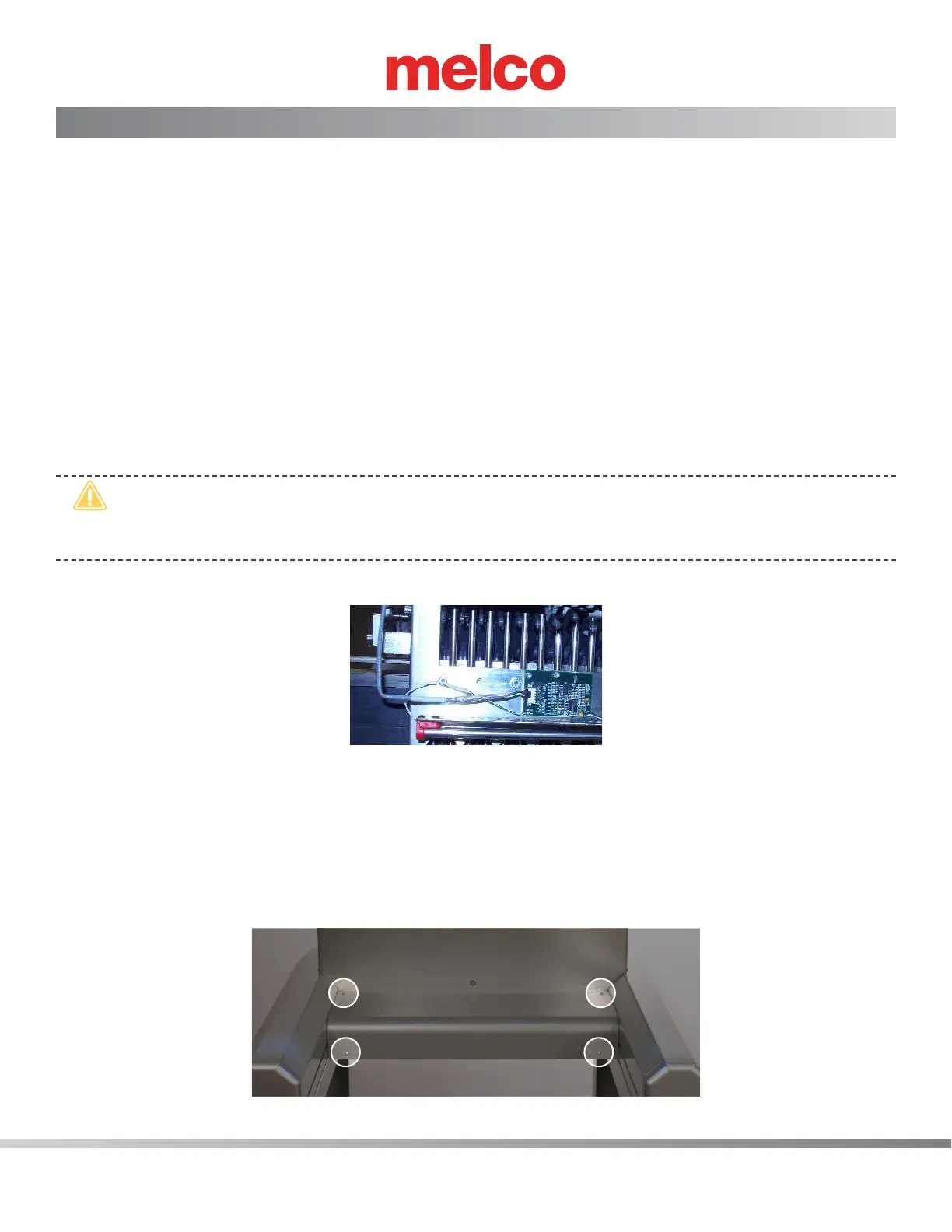
Figure 1 - Threadbreak Harness Connected to Sensor PCB
5. Disconnect the thread break harness from the thread break sensor PCB.
6. Power down the machine and disconnect the A/C power input cord and the external Ethernet
cable from the back of the machine.
7. Remove cover for the main PCB.
a. Remove the 4 screw(s) that hold the main PCB cover in place.

 Loading...