210 of 289
b. Remove the PCB cover.
•
CAUTION!! Be careful not to drop metallic hardware or tools onto the Main PCB while it is
exposed. Doing so can result in severe damage to the electronics that might be expensive to
repair.
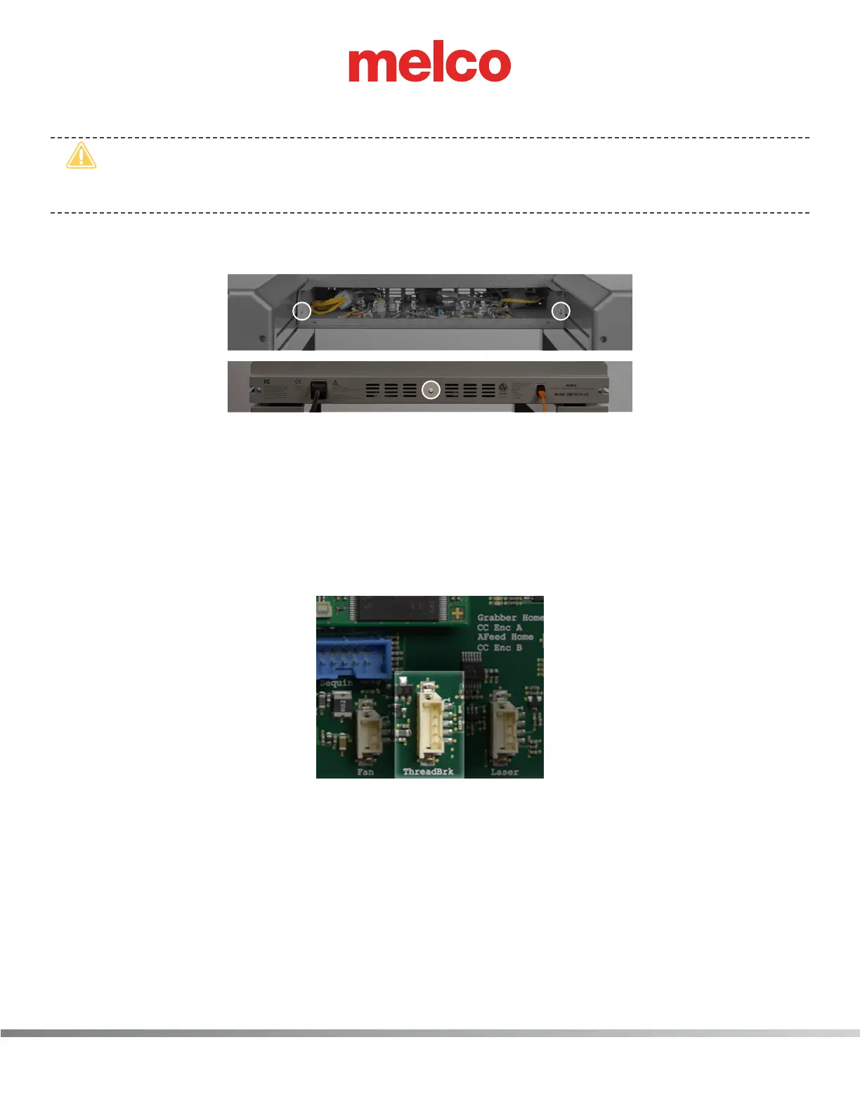
c. Once the main PCB cover is removed loosen but do not remove the 2 PCB securing tray screws
in the front and fully remove the securing plate screw in the rear.
8. Gently slide the main PCB mounting tray forward to gain full access to the main PCB.
9. Remove all the twist-lock cable ties that tie it to the adjacent harnesses all the way up to the front
of the thread tree base.
10. Remove the twist-lock cable tie that bundles the harnesses behind the thread tree base and pull
the thread break harness through from the back of the thread tree base.
11. Pull the harness to the back of the machine, remove any twist-lock cable ties that bundle it to
adjacent harnesses, all the way down to the right access hole to the Main PCB.
Figure 3 - Connection at Main PCB
12. Disconnect the thread break harness from the connector socket at location “ThreadBrk” on the
Main PCB and cut any remaining cable ties bundling the thread break harness to adjacent har-
nesses. Remove the harness from the machine.
13. Connect the end of the thread break harness labeled “THREAD BREAK SENSOR PCB” to the con-
nector socket on the thread break sensor PCB.
 Loading...
