176 of 289
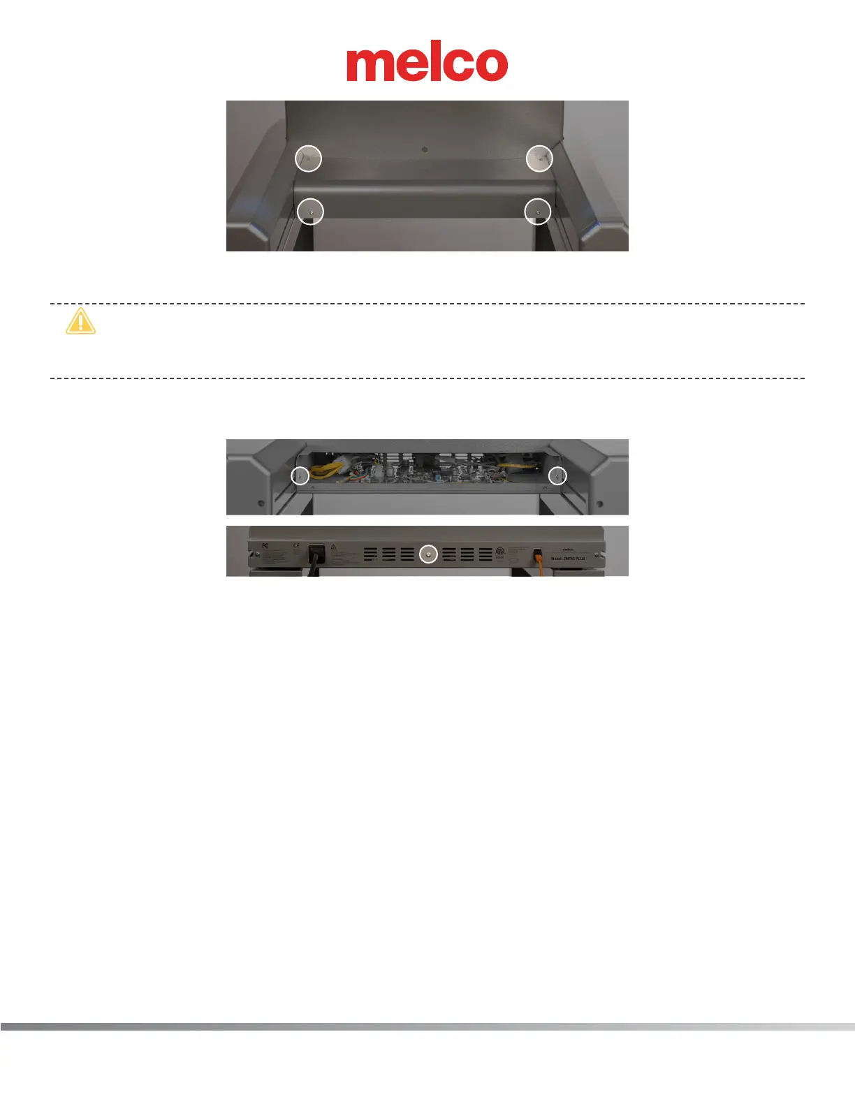
b. Remove the PCB cover.
•
CAUTION!! Be careful not to drop metallic hardware or tools onto the Main PCB while it is
exposed. Doing so can result in severe damage to the electronics that might be expensive to
repair.
c. Once the main PCB cover is removed loosen but do not remove the 2 PCB securing tray screws
in the front and fully remove the securing plate screw in the rear.
d. Gently slide the main PCB mounting tray forward to gain full access to the main PCB.
4. One at a time disconnect all of the harnesses from the Main PCB and leave the connector in close
proximity to the connector socket where you removed it from.
5. Remove the M4 X 8mm anged socket head screws mounting the Main PCB to the machine base.
6. Remove the Main PCB from the base handling it only by the edges (especially if it is going to be
sent to Quality Assurance for failure analysis).
7. Place the old Main PCB in a protective anti-static bag.
8. Remove the replacement Main PCB from the protective anti-static bag it was shipped in, handling
it only by the edges and place it in position on the machine base.
9. Install the M4 X 8mm anged socket head screws and tighten the screws to minimum the torque
specications (only enough to secure the Main PCB in position).
10. One at a time, connect all of the harnesses to their corresponding sockets on the Main PCB.
11. Replace the EMI cover carefully.
12. Turn the machine ON.
 Loading...
