180 of 289
5. Using a small at blade screw driver press in on the spring clips located on the top right and left
side of the power input. Remove the power input out the back of the PCB mounting tray.
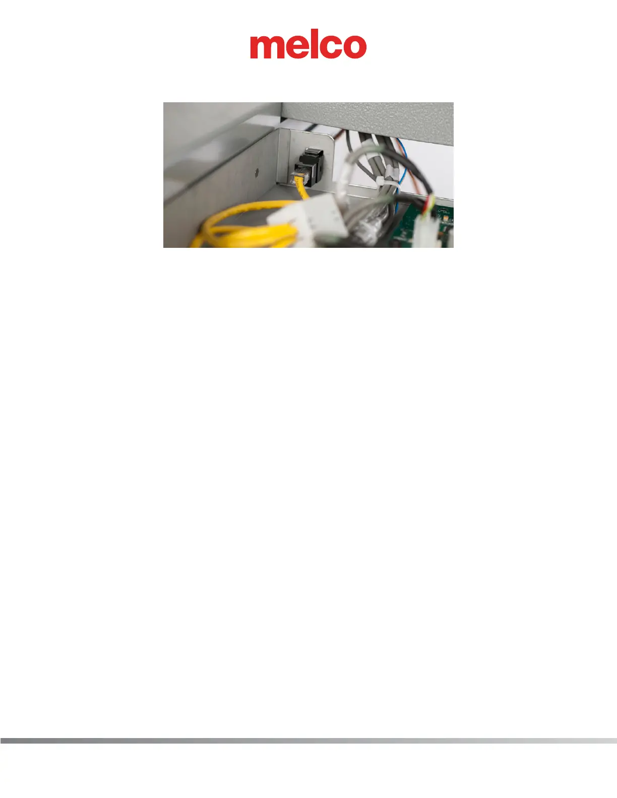
6. Disconnect the network cable by pressing down the retaining clip.
7. From the rear of the PCB mounting tray, press down the retaining clip located on the top side of
the in-line coupler. The in-line coupler will be removed from the PCB mounting tray towards the
front of the tray.
8. Install both components by following previous steps in reverse order.
 Loading...
