201 of 289
•
CAUTION!! Use extreme care not to drop metallic objects, tools, or other conductive material
on the Main PCB when you have the base cover removed. If you drop such objects on the Main
PCB, it can severely damage the electronics which will be very expensive to repair.
6. Remove the base cover, upper arm back cover and the lower arm rear cover.
7. Remove any twist-lock cable ties that bundle the grabber/threadfeed/cc harness to adjacent ones
behind the needle case assembly and any cable ties that tie the connectors to the PCBs. Set them
aside for re-use.
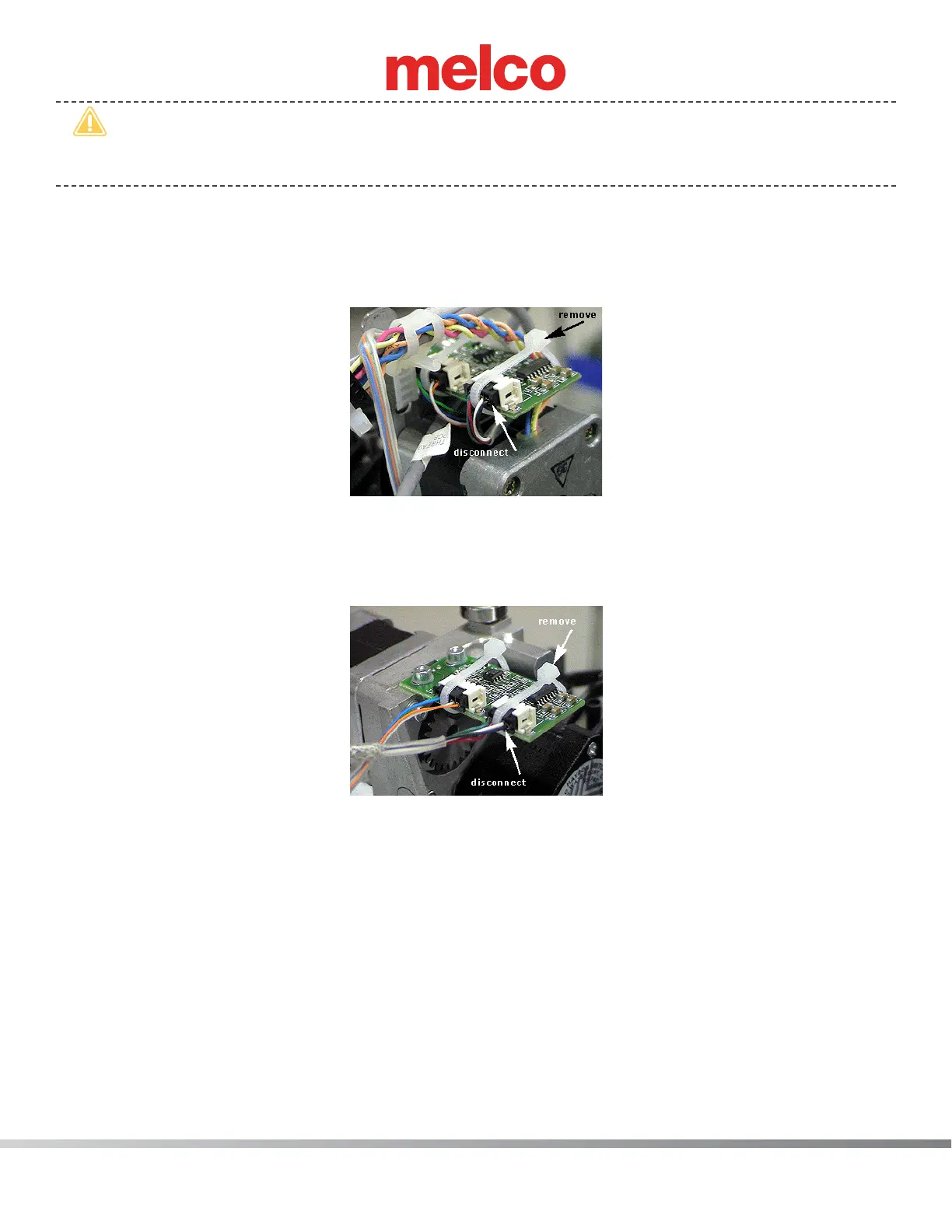
Figure 1 - Grabber Home Harness Lead
8. Disconnect the grabber/threadfeed/cc harness from the grabber home PCB located at the top left
behind the needlecase. The grabber/threadfeed/cc harness lead is the four pin connector. The ve
pin connector is the grabber stepper motor interface cable.
Figure 2 - Thread Feeder Home PCB
9. Disconnect the grabber/threadfeed/cc harness from the thread feeder home PCB located at the
top center right behind the needlecase assembly (on the right above the thread feeder stepper
motor). The grabber/threadfeed/cc harness threadfeed home lead is the four pin connector identi-
ed in Figure 2 above. The ve pin connector is for the stepper motor interface cable.
10. Remove any twist-lock cable ties bundling the harnesses together behind the thread tree base and
pull the grabber/threadfeed/cc harness from under the thread tree base all the way to the back
down to the right lower arm access hole.
 Loading...
