Terminal Test Probe Kit Bosch P/N MM‑ 46523
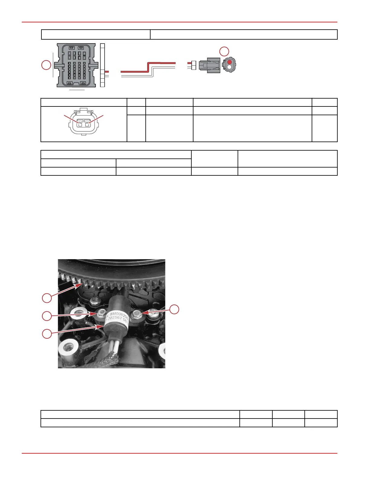
a - PCM connector A
b - Crankshaft position sensor
connector
Connector Pin Wire Color Function PCM
1 Red Crankshaft position sensor + AC4
2 White Crankshaft position sensor – AD4
Meter Test Leads
Meter Scale Reading
Red Black
Connector A, pin C4 Connector A, pin D4 Auto 300–350 Ω at 21 °C (70 °F)
Crankshaft Position Sensor Removal
1. Remove the cold air intake assembly:
a. Remove the oil level dipstick.
b. Loosen the hose clamp at the top of the throttle body assembly.
c. Lift the assembly up to disengage the two pins from the grommets on the oil fill bracket.
d. Swing the assembly out of the way.
2. Remove the oil fill bracket, alternator, and alternator belt. Refer to the appropriate service manual.
3. Disconnect the sensor harness from the engine harness.
4. Remove two M5 x 13 hex washer head screws, and remove the sensor.
a - Crankshaft position sensor
b - M5 x 13 hex washer head screws (2)
c - Flywheel
Crankshaft Position Sensor Installation
NOTE: Refer to the preceding illustration, as required.
1. Position the sensor on the engine, and secure the sensor with two M5 x 13 hex washer head screws. Tighten the screws to
the specified torque.
Description
Nm lb‑in. lb‑ft
M5 x 13 hex washer head screw 5 44.3 –
2. Connect the sensor harness to the engine harness.
3. Install the alternator, alternator belt, and oil fill bracket. Refer to the appropriate service manual.
RED
RED
WHT
WHT
1
2
H4
D4
A1
C4
Sensors
Page 5A-16 © 2018 Mercury Marine 90-8M0146617 eng JULY 2018
 Loading...


