Analog Gauges (DTS only)
All PCM 112 engines have the ability to drive analog gauges without the need for an external analog gauge interface (AGI).
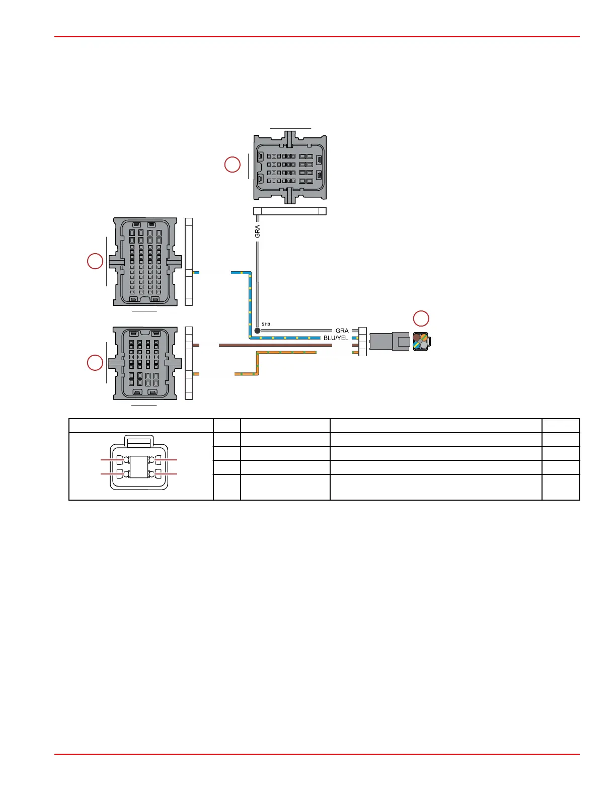
However, DTS engines are unable to send these signals up the 14‑pin harness and require an additional 4‑pin analog gauge
harness to be routed to the dash. Use the following wire diagram to troubleshoot the engine harness side if a problem is
detected. CDS G3 can also display the voltage parameters for the signal being sent to the coolant, oil pressure, and trim
position gauges under the vessel tab of the live data display.
a - PCM connector A
b - PCM connector B
c - PCM connector C
d - Analog gauge connector
Connector Pin Wire Color Function PCM
1 Gray Tachometer signal AA1
2 Blue/yellow Oil pressure analog gauge BL3
3 Brown Coolant temperature analog gauge CD1
4 Orange/green Trim position analog gauge CA3
IMPORTANT: Refer to CDS G3 for the tachometer, oil pressure, coolant temperature, and trim position output values.
BLU/YEL
BRN
BRN
ORN/GRN
ORN/GRN
1
2
3
4
A3
D1
H4
A1
L3
A1
M4
A1
H4
H
A
4
1
A B
C
D E F G H
J
K
AB
C
DE
FGH
J
K
1
3
2
4
L
M
L
M
Accessories
90-8M0146617 eng JULY 2018 © 2018 Mercury Marine Page 5C-7
 Loading...


