a - Propulsion control module (PCM), connector A
b - Main power relay
c - Hot stud
d - Engine fuses
e - Coil harness connector
f - Ignition coil adapter harness
g - Coil A connector (cylinders 1 and 4)
h - Coil D connector (cylinders 3 and 8)
i - Coil C connector (cylinders 6 and 7)
j - Coil B connector (cylinders 2 and 5)
Connector Pin Wire Color Function PCM
A Green/brown Coil A AH4
B Green/red Coil B AH3
C Green/purple Coil C AH2
D Green/yellow Coil D AH1
E Red/yellow Fused (20 A) 12 V power (+) –
Hot stud ring terminal – Red 12 V battery power (+) –
MPR 86 Yellow/purple Main power relay (MPR) control signal AA2
MPR 87 Red/white Switched 12 V power (+) –
Ignition coil B A Red Fused (20 A) 12 V power (+) –
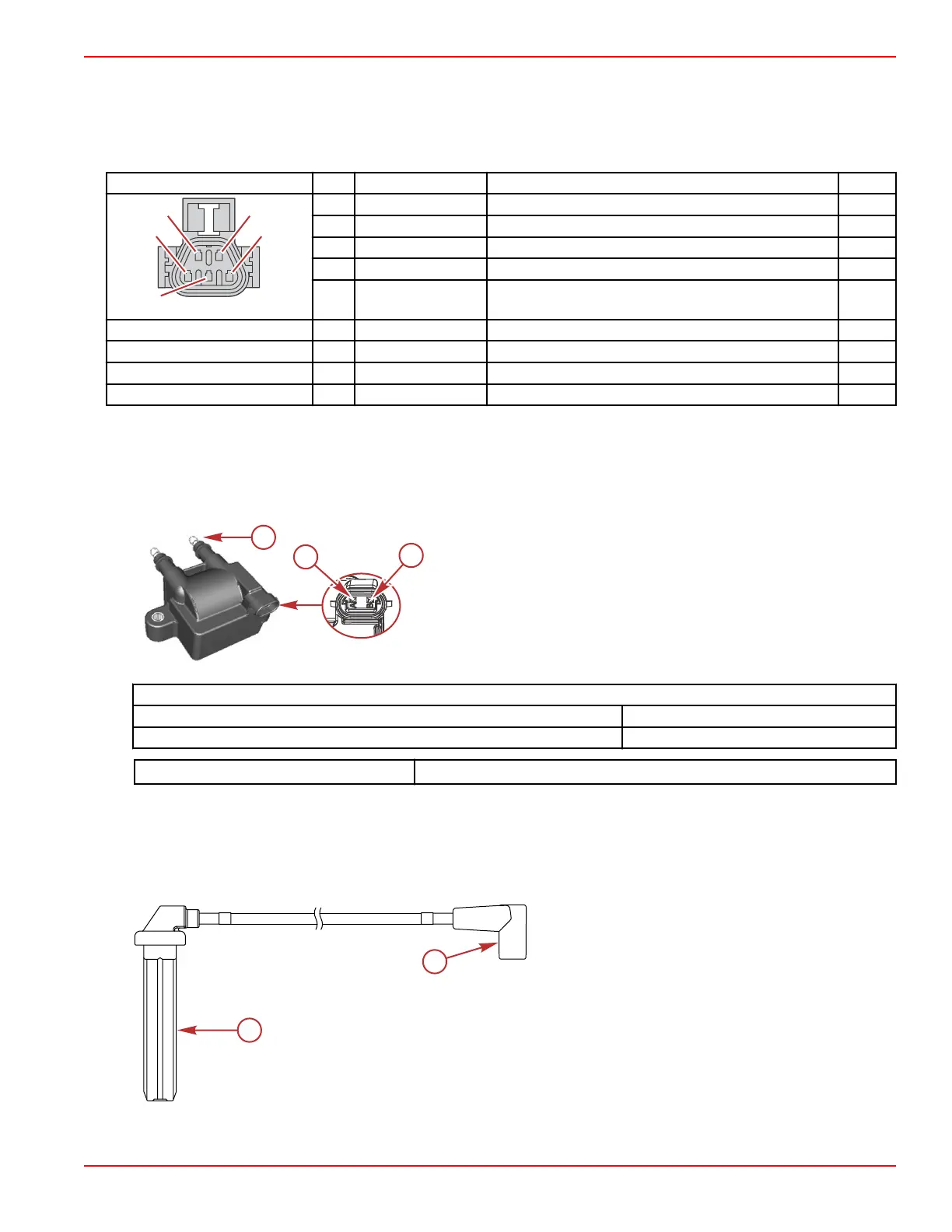
Ignition Coil Resistance Test
1. Remove the spark plug lead from the ignition coil. Twist the ignition coil boot slightly while removing.
2. Use a DMT 2004 digital multimeter and perform the following test.
a - Pin A
b - Pin B
c - Coil towers
Ignition Coil Resistance Test (Ω)
Between coil towers 7200–8800
Between pin A and B 0.3–0.5
DMT 2004 Digital Multimeter 91‑892647A01
Spark Plug Wires
The spark plug wires are of differing lengths, and therefore have different resistance values. The cylinder number is clearly
marked on each end of every spark plug wire. Always ensure that you use the correct wire to connect a given spark plug to its
corresponding ignition coil. After installing each spark plug wire, ensure that the terminal has engaged by lightly tugging on
each connection.
a -
Spark plug end
b - Ignition coil end
Ignition
90-8M0146617 eng JULY 2018 © 2018 Mercury Marine Page 6A-7
 Loading...


