Intake Manifold Air Temperature Sensor Resistance Test
Temperature Reading
0 °C (32 °F) 6.18–6.83 kΩ
15 °C (59 °F) 3.04–3.36 kΩ
25 °C (77 °F) 2.00–2.21 kΩ
100 °C (212 °F) 0.14–0.16 kΩ
4. Perform a continuity check of the sensor wiring between the sensor connector and the PCM. Note that there are splices in
the sensor ground circuit.
NOTE: The quickest way to check the wiring is to measure the resistance of the thermistor at room temperature, connect
the sensor to the engine harness, and measure the resistance across PCM connector sockets CE1 and BL2. If the two
resistance values match, then the wiring is good.
DMT 2004 Digital Multimeter
91‑892647A01
Terminal Test Probe Kit Bosch P/N MM‑ 46523
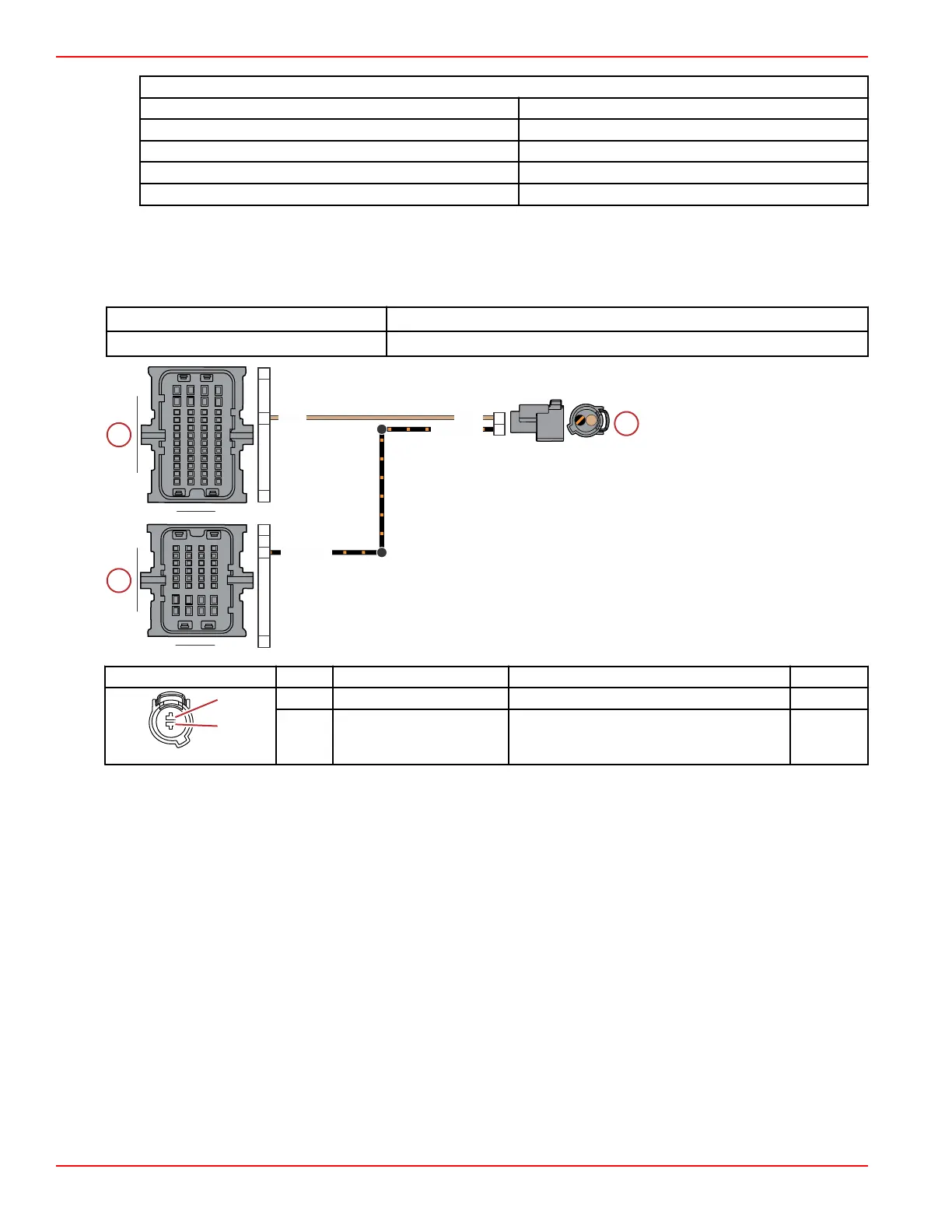
a - Intake air temperature (IAT)
sensor connector
b - PCM connector B
c - PCM connector C
Connector Pin Wire Color Function PCM
A Tan Air temperature signal BL2
B Black/orange Sensor ground A (–) CE1
IAT Sensor Removal
1. Remove the starboard air intake runner. Refer to the appropriate service manual.
2. Disconnect the engine harness connector from the IAT sensor.
100A
100B
BLK/ORN
TAN
TAN
BLK/ORN
A
B
H4
E1
A1
L2
M4
A1
A B
C
D E F G H
J
K
AB
C
DE
FGH
J
K
1
3
2
4
L
M
L
M
Sensors
Page 5A-24 © 2018 Mercury Marine 90-8M0146617 eng JULY 2018
 Loading...


