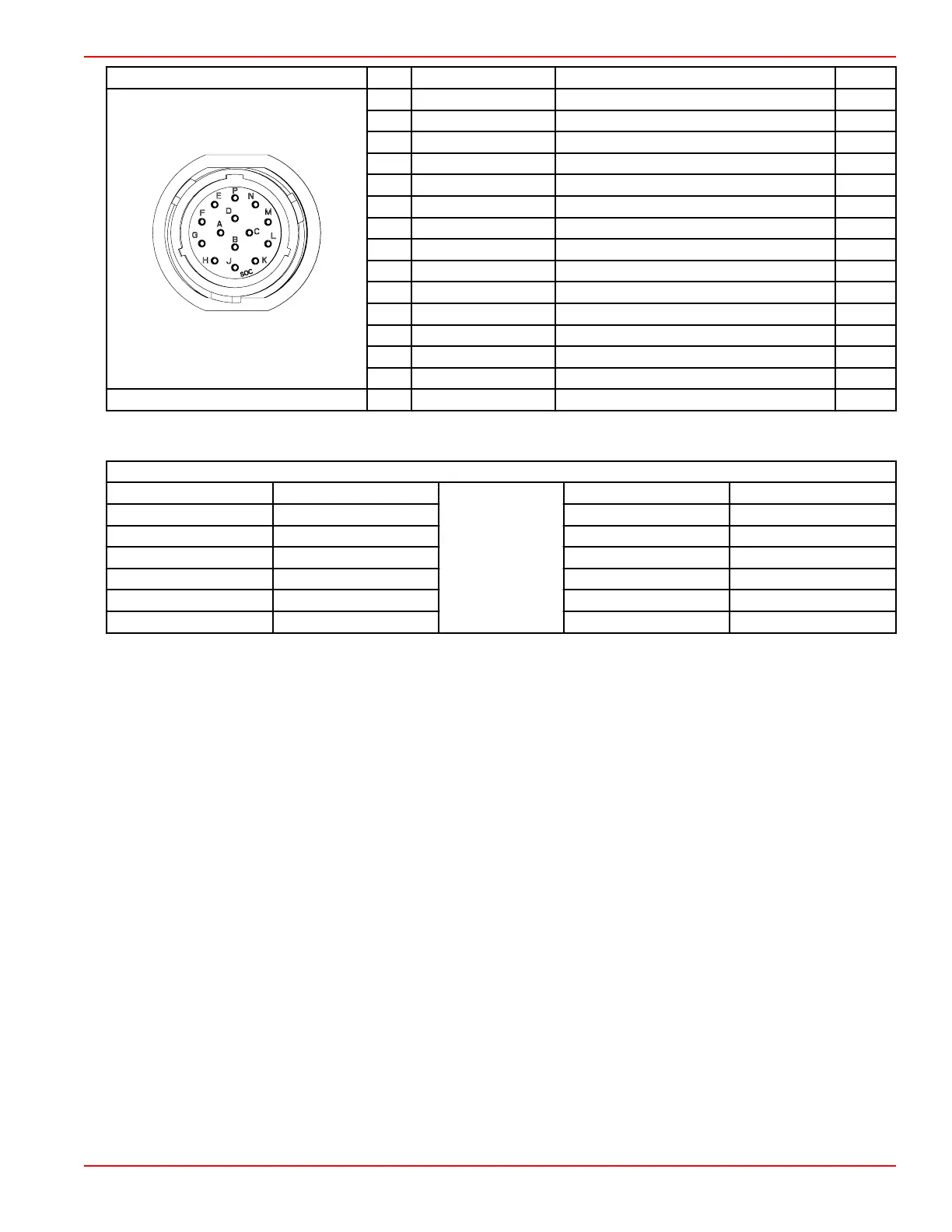
Connector Pin Wire Color Function PCM
A Red/black 12 V clean power (+) –
B Black Clean power ground (–) –
C Purple 12 V wake circuit (+) CC1
D Black/yellow E‑stop signal AD3
E Orange/green CAN H high –
F White CAN P high BG2
G Blue CAN P low BG1
H Red/purple Fused (15 A) 12 V power (+) –
J Black Chassis ground (–) –
K Yellow CAN X high BH2
L Brown CAN X low BH1
M Gray Tachometer signal AA1
N N/A Not used –
P Green/orange CAN H low –
Hot stud ring terminal – Red 12 V battery power (+) –
Wire Color Code Abbreviations
Wire Color Abbreviations
BLK Black
BLU Blue
BRN Brown GRY or GRA Gray
GRN Green ORN or ORG Orange
PNK Pink PPL or PUR Purple
RED Red TAN Tan
WHT White YEL Yellow
LT or LIT Light DK or DRK Dark
SmartCraft Circuit Diagrams
90-8M0146617 eng JULY 2018 © 2018 Mercury Marine Page 8A-3
 Loading...


