Pitot Pressure Sensor Installation
1. Install the sensor adapter onto the pitot pressure sensor. Tighten the sensor adapter to ensure the adapter will not leak.
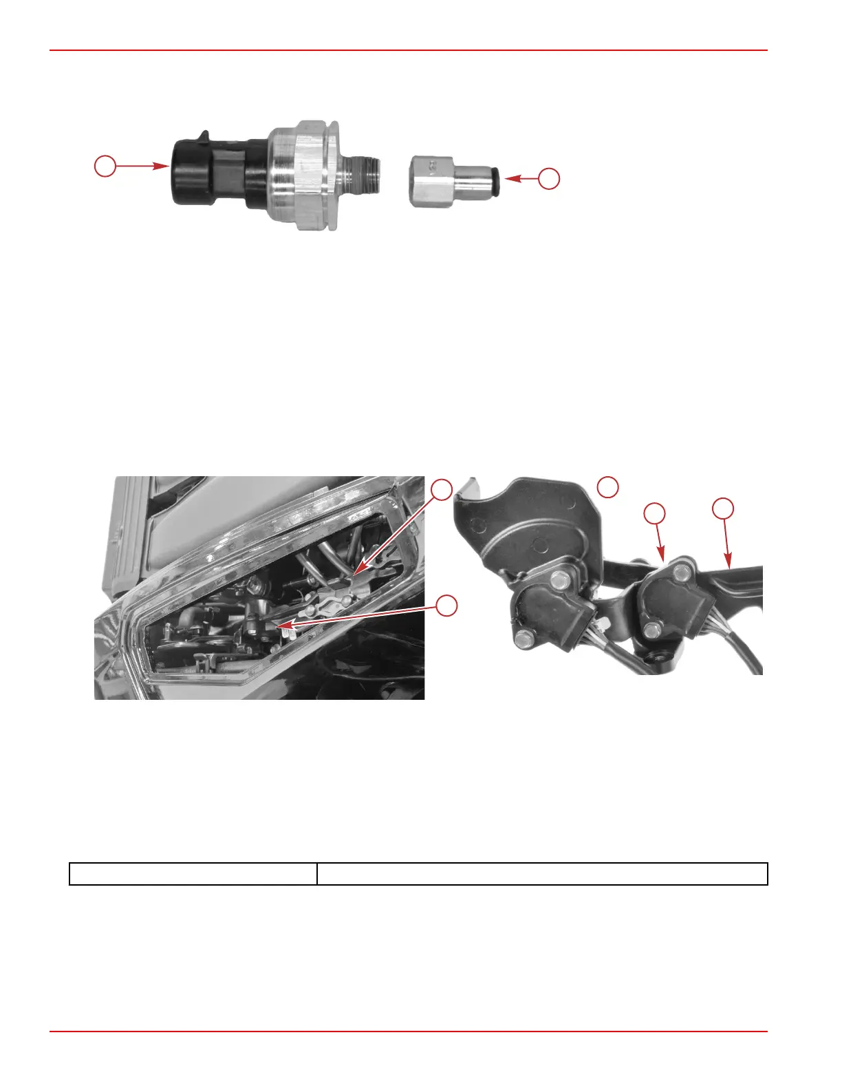
a - Pitot pressure sensor
b - Sensor adapter
2. Connect the engine harness to the sensor.
3. Connect the pitot tube.
4. Use a cable tie to secure the sensor to the engine harness.
5. Install the port intake runner. Refer to the appropriate service manual.
Shift Demand Sensor
NOTE: The shift demand sensor is only on models with mechanical throttle and shift controls.
The demand sensors used for the throttle and shift demand are identical. They consist of two hall‑effect sensors in a single
housing, configured such that the value of the output signal of one sensor increases (from 0.5 VDC to 4.5 VDC) as the other
decreases (from 4.5 VDC to 0.5 VDC), and vice versa.
The sensors can be swapped for diagnostic purposes. Exercise special care to ensure that the sensor connections to the
engine harness are correct, prior to attempting to run the engine.
The shift demand sensor is the foremost of the two sensors on the throttle and shift bracket.
a - Throttle and shift bracket
b - Shift demand sensor
c - Underside of throttle and shift bracket
Shift Demand Sensor Testing
Monitor the operation of the shift demand sensor by viewing the CTRL_Gear and ActualGear data items on the CDS G3 Live
Data screen. If the shift demand sensor is operating correctly and with the engine running, both items should indicate the gear
as requested by the remote control.
CDS G3 Interface Kit
8M0138392
If the value of CTRL_Gear does not change as the shift lever is moved between forward, neutral, and reverse, shake or move
the sensor harness and connector. If the value of CTRL_Gear begins to change, look for a broken, loose, or corroded wire.
Continue testing with the engine OFF:
1. Disconnect the engine harness connector from the shift demand sensor.
2. Visually inspect the sensor pins and the wires coming from the engine harness connector. Look for broken, bent, or
corroded pins at the sensor and loose, broken, or corroded wires at the engine harness connector.
Sensors
Page 5A-38 © 2018 Mercury Marine 90-8M0146617 eng JULY 2018
 Loading...


