The alternator is equipped with two fans that induce air flow through the alternator to remove heat.
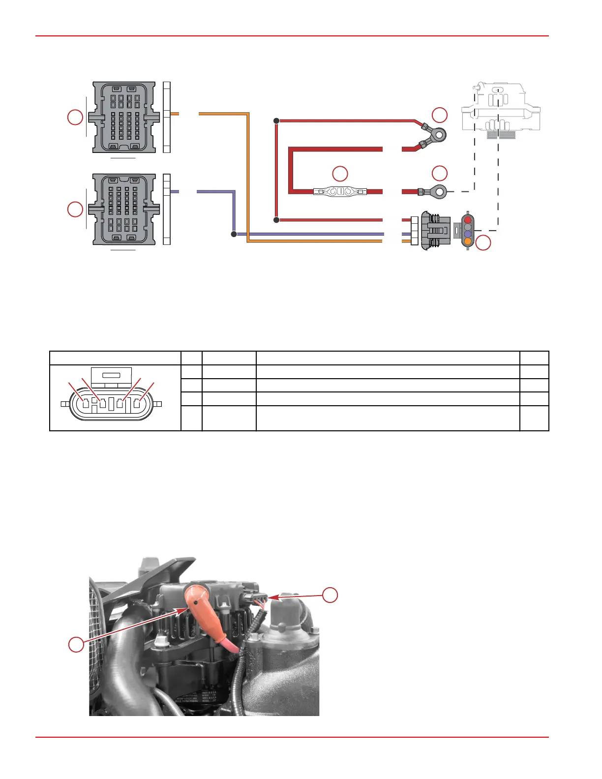
Alternator
a - PCM connector A
b - Hot stud (battery +)
c - PCM connector C
d - Fusible link
e - Alternator output
f - Alternator 4‑pin connector
Connector Pin Wire Color Function PCM
A Orange Not connected at the alternator; not used AG2
B N/A Not used –
C Purple 12 V wake circuit (+) ‑ used as the excitation lead CC1
D Red 12 V battery power (+) ‑ used as the alternator sense lead –
Charging System Inspection
1. If the problem is an undercharged battery, verify the condition has not been caused by excessive accessory current draw
or by accessories that have been left on.
2. Check the physical condition and state of charge of the battery. The battery must be at least 75% (1.230 specific gravity)
charged to obtain valid results in the following tests. If not, charge the battery before testing the system.
3. Inspect the entire charging system wiring for defects. Check all connections for tightness and cleanliness, particularly the
battery cable clamps and battery terminals.
IMPORTANT: The alternator output lead (black with red sleeve) connection must be tight. A darkened red sleeve indicates
the lead was loose and became hot. Verify the output lead attaching nut is tightened to the specified torque.
a - Alternator output lead/fusible link, to hot stud
b - Alternator connection to engine harness
(excitation and sense leads)
109B
109A
102B
PPL
ORN
RED
PPL
RED
ORN
RED
C1
A1
H4
A1
H4
G2
A
B
C
D
Charging and Starting System
Page 6B-6 © 2018 Mercury Marine 90-8M0146617 eng JULY 2018
 Loading...


