3. Remove the two M5 x 16 hex washer head screws that secure the throttle demand sensor to the underside of the throttle
and shift bracket, and remove the sensor.
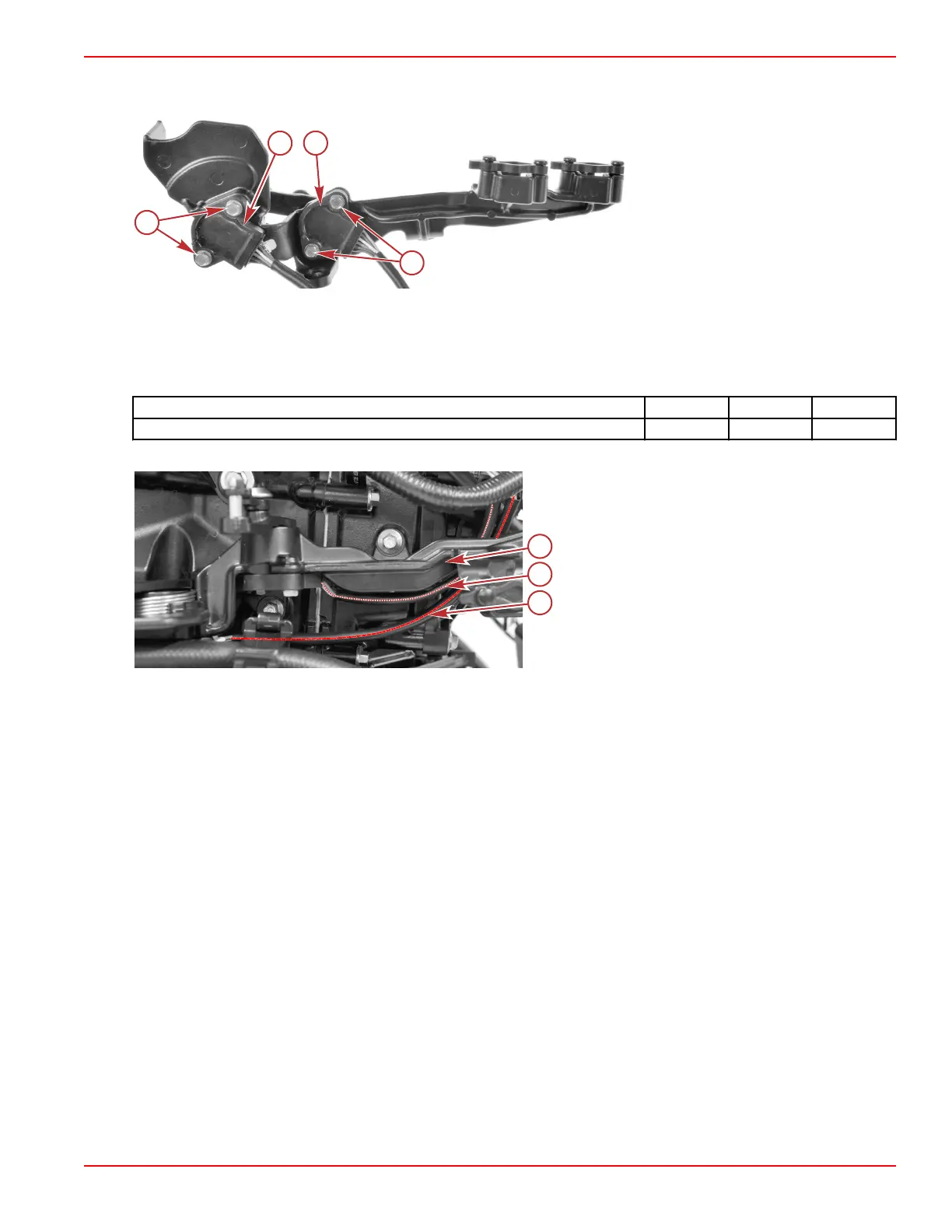
Throttle and shift bracket, shown
removed for clarity
a - M5 x 16 hex washer head screws (2
per sensor, 4 total)
b - Throttle demand sensor
c - Shift demand sensor
Throttle Demand Sensor Installation
NOTE: Refer to previous illustrations as required.
1. Attach the throttle demand sensor to the underside of the throttle and shift bracket, using two M5 x 16 hex washer head
screws. Tighten the screws to the specified torque.
Description
Nm lb‑in. lb‑ft
M5 x 16 hex washer head screw 1.7 15 –
2. Route the throttle demand sensor harness between the throttle and shift bracket and the engine block.
a - Throttle and shift bracket
b - Shift demand sensor harness
c - Throttle demand sensor harness
3. Connect the throttle demand sensor harness to the engine harness. Use a cable tie to secure the connection to the engine
harness.
Trim Position Sensor
For information on the trim position sensor, refer to the appropriate section of this manual:
• Section 6C ‑ Conventional Midsection (CMS) Power Trim
• Section 6D ‑ Advanced Midsection (AMS) Power Trim
Water‑in‑Fuel (WIF) Sensor
IMPORTANT: SeaPro models are equipped with a vessel mounted water‑separating fuel filter that has a water‑in‑fuel (WIF)
sensor located on the filter drain knob. The engine mounted WIF sensor on SeaPro models is disconnected and is not used.
The water‑in‑fuel (WIF) sensor is a normally open switch with two highly conductive probes. Water completes a 5‑volt negative
reference to the PCM. When water is present, the PCM generates an error history and activates a warning horn to inform the
operator. If SmartCraft gauges are installed, the display will flash a visual warning to the operator.
Sensors
90-8M0146617 eng JULY 2018 © 2018 Mercury Marine Page 5A-43
 Loading...


