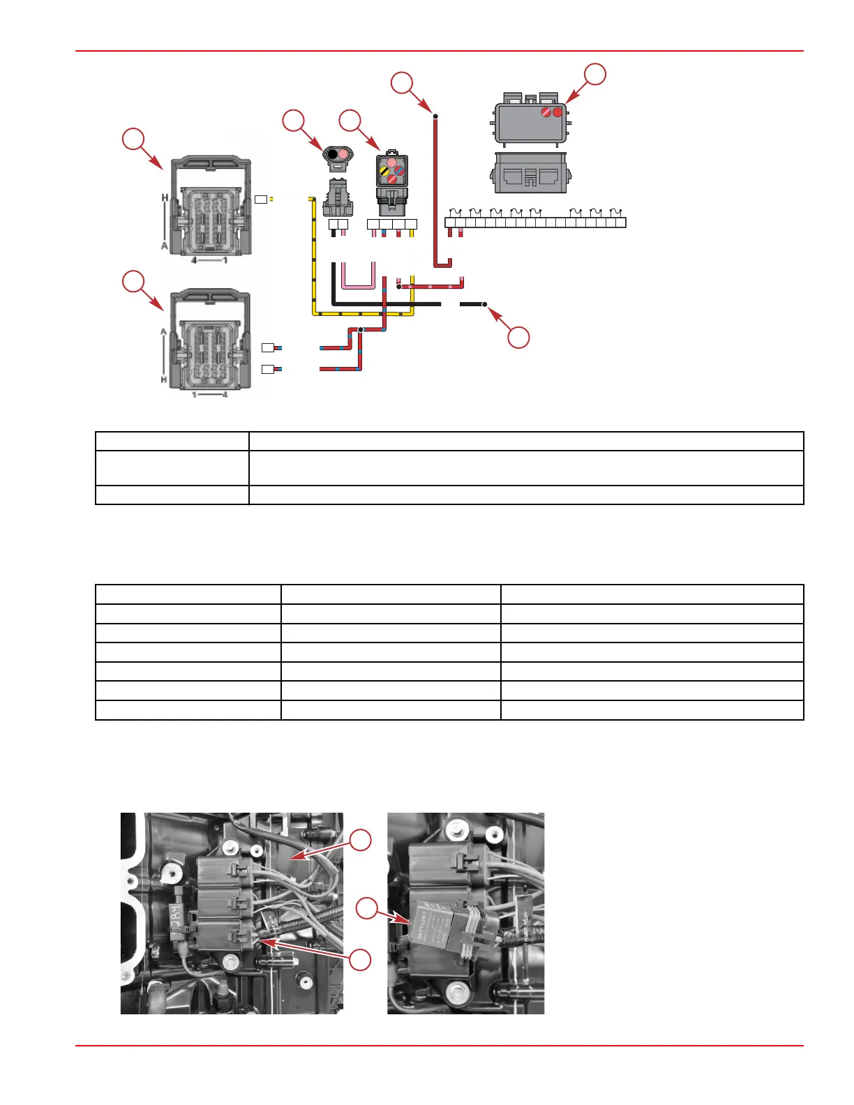
a - PCM connector A
b - PCM connector C
c - Fuel pump connector
d - Fuel pump relay
e - 12 volt to fuse
f - Fuses
g - Ground
The following table identifies the function of each fuel pump relay contact point:
Contacts
Description
85 and 86
Coil contacts. Grounds the PCM connection and activates the relay, which closes the circuit
contacts.
30 and 87 Circuit contacts. When the coil is activated these contacts form a closed circuit.
The fuel pump relay receives driver power from the red/blue wire. The PCM grounds pin AB4 (yellow/black wire) to complete
the driver power circuit and close the fuel pump relay. If the PCM does not detect an RPM signal, the pump will turn off after
several seconds. When the relay is closed, battery power flows from the fuse on the red/pink wire and through the relay to the
fuel pump on the pink wire.
Wire Color Code
PCM Connector Pin Function
Yellow/black AB4 Fuel pump relay control
Red/blue CG3 and CG4 Driver power
Pink – Fuel pump power from relay
Black – Engine ground
Red/pink – 12 V from fuse
Red – 12 V to fuse
Main Power Relay (MPR)
The main power relay (MPR) is activated by the PCM and supplies power to the ignition and fuel injection components through
the fuse block. The relay is supplied with power from the hot stud and positive battery cable. It is located behind the starboard
intake runner. To remove and install the starboard intake runner, refer to the appropriate outboard service manual.
a -
Starboard side of powerhead,
intake runner removed
b - MPR socket on the engine
harness
c - MPR
BLK
RED/BLU
RED/PNK
RED/PNK
PNK
/
D
E
R
U
L
B
U
L
B
/
D
E
R
G3
G4
87 8530
B
B4
K
L
B
/
L
E
Y
YEL/BLK
b
c
d
e
f
g
20A 10A 2A
15A 20A 5A 20A
20A
A1
A2
A3
A4
A5
A6
B1
B2
B3
B4
B5
B6
C1
C2
C3
C4
C5
C6
B6 B5 B4 B3
B2
B1
C6
C5
C4
C3 C2
A6 A5
A4
A3 A2 A1
C1
66816
a
Actuators and Relays
90-8M0146617 eng JULY 2018 © 2018 Mercury Marine Page 5B-5
 Loading...


