Tools required.
M4 hex socket wrench
or 7mm nut runner.
Spacer kit
Discharge Tool
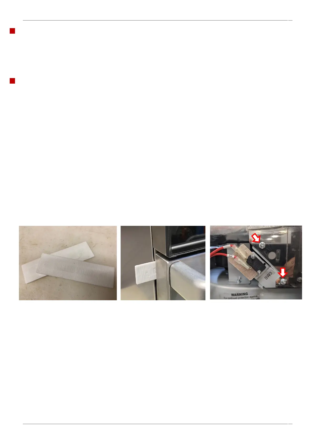
Adjusting the door microswitches.
Located on the door hinge brackets are 3 safety interlock microswitches, to prevent microwave emissions escaping when the
oven door is opened:
▪ The primary microswitch (SW3), located on the left-hand side of the oven, breaks the electrical supply circuit to
the HV transformers.
▪ The secondary microswitch (SW2), located on the right-hand side of the oven (outer), breaks the microwave
circuit if the primary (SW3) fails.
▪ The monitor microswitch (SW1), located on the right-hand side of the oven (inner), will short out the microwave
circuit, blowing the F5 / F6 fuse, if the secondary microswitch (SW2) fails closed circuit.
IMPORTANT:
If the monitor switch (SW1) causes the microwave circuit F6 / F7 fuse to blow, the secondary (SW2) and monitor (SW1)
microswitches must be replaced due to exposure to high short-circuit currents.
The purpose of the following adjustment procedure is to set the interlock to switch off the microwave circuit when the door is
opened more than 5 mm and for the microwave circuit to operate when the door is closed, and the door seal expands.
1. Open the appliance door and position the two 3mm spacers over the top corners of the door seal. Then carefully close
the door ensuring the spacers are still in position.
2. Loosen the left interlock adjuster nuts, SW3 (Arrowed).
3. The switch bracket can now be rotated around the top screw.
4. Move the microswitch bracket until it just operates the switch.
5. As soon as the primary door switch (SW3) closes, nip up the two flange head nuts to 2.1Nm.