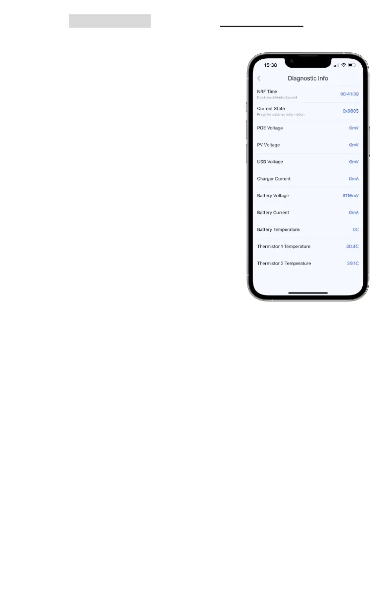
v. Tap Diagnostic Log to enter the Diagnostic Info tab where
measurements can determine certain issues a node may
have, like charging or overheating.
1. NRF Time: uptime of the power
management system. Under
normal circumstances, this
circuit will not reset. A short
value is an indication that a fault
occurred and power cycled the
board, resetting the clock
2. Current State: this hex value
corresponds to the internal
state machine and can be
communicated to us during
debugging efforts to identify
the power management mode
3. PoE Voltage: the input PoE
voltage in mV. if a PoE PD
power module is connected to
the node, its readout should
appear as roughly 19,000 mV
4. PV Voltage: the input adapter or solar panel voltage in
mV. This should be roughly 12,000 mV for 12V modes and
18,000-22,000 mV for default solar input
5. USB Voltage: the USB bus voltage in mV. This should be
roughly 20,000 mV if charging over USB-C-Power Delivery
6. Charger Current: the input current in mA. This can be up
to 4,000mA. If this is consistently lower than 300mA, the
power may not be high enough to keep the node on.
7. Battery Voltage: the standard voltage should read
7,800-8,400 mV. If the voltage is under 7,000 mV, the
batteries are in a protection state and require resetting
8. Battery Current: the charging current in mA. This can be
up to 7,000mA. If negative, the battery is discharging;
otherwise, it is charging. A node that has a consistently