N ELECTRICAL
EqUIPMENT-~--
commutator
end
bracket
and
remove
the
bracket
from
the
dynamo yoke.
The
driving end bracket,
together
with
the
arrna-
cure, can now be lifted
out
of
the
yoke.
The
driving end
bracket
which, on removal from
the
yoke, has
withdrawn
with It
the
armature
and
armature
shaft ball bearing. need
not
be
separated
from
the
shaft unless
the
bearing is suspected and
requires
examination, in which
event
the
armature
should be
removed from
the
end
bracket
by means of a hand
press.
Seetlon
N.5
SERVICING THE
DYNAMO
Brushes
Test
if
the
brushes
are
sticking. Clean
them
with
petrol
and. If necessary, ease
the
sides by lightly
pollsh[ng with a
smooth
file. Replace
the
brushes in
their orlgl nal positlo ns.
Test
the
brush spring tension with a
spring
scale if
available. The
correct
tension ls 20/25 oz.
(567{709
grams). Fit a new spring if
the
tension Is low.
If
the
brushes
are
worn
so
that
the
flexible is exposed
on
the
running face, new brushes must be fitted.
Brushes
are
pre-formed so
that
bedding
to
the
com-
mutator
is unnecessary.
Commutator
A
commutator
In good condition will be
smooth
and
free from pits
or
burned
spots. Clean
the
com-
mutator
with a petrol-moistened cloth. If this Is
RIGHT
WAY
WRONG
WAY
fig. N.6.
The
correct
method of
undercutting
the
dynamo
commutator
segments.
ineffective. carefully polish with a
strip
of fine glass-
paper
while
rotating
the
armature.
To remedy a
badly
worn
commutator,
mount
the
armature
(with
or
without
the
drive end bracket) in a lathe,
rotate
at
high speed and
take
a light
cut
with a very sharp tool.
Do
not
remove
more
metal
than
is necessary. Polish
the
commutator
with very fine glass-paper.
Undercut
the
Insulators
between
the
segments
to
a
depth
of
n In. (·8 mm.) with a hack-saw blade
ground
down
to
the
thickness of
the
insulator.
N.6
Field
coils
Test
the
field coils.
without
removing
them
from
the
dynamo yoke, by means of an
ohmmeter.
The
reading on
the
ohmmeter
should be
between
6·0 and
6·3 ohms. If this Is
not
available, connect a 12-volt.
D.C. supply with an
ammeter
In series
between
the-
field
terminal
and dynamo yoke.
The
ammeter
reading should
be-
apprcxtrnaeely 2 amps. If no
reading Is Indicated
the
field coils
are
open-circuited
and must be renewed. To
test
for
earthed
field coils.
unsolder
the
end of
the
field winding from
the
earth
/
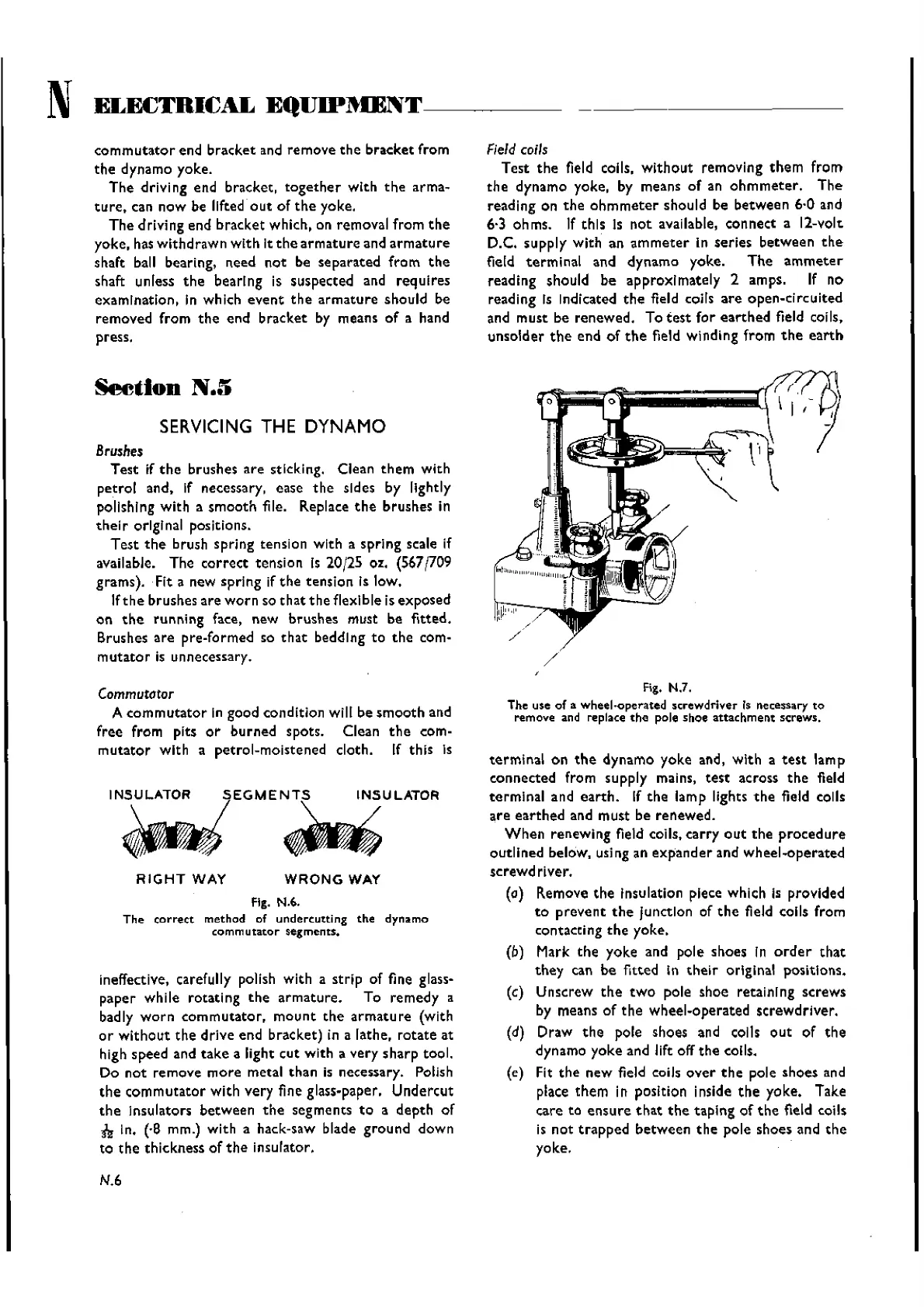
Fig. N.7.
The use of a
wheel-operated
screwdriver Is necessary
to
remove and replace
the
pole shoe
attachment
screws.
terminal
on
the
dynamo yoke and, with a
test
lamp
connected from supply mains,
test
across
the
field
terminal
and
earth.
If
the
lamp lights
the
field calls
are
earthed
and must be renewed.
When
renewing field coils.
carry
out
the
procedure
outlined below. using an
expander
and wheel-operated
screwdriver.
(0)
Remove
the
Insulation piece which Is provided
to
prevent
the
Junction of
the
field coils from
contacting
the
yoke.
(b) Mark
the
yoke and pole shoes ln
order
that
they
can be fitted in
their
original positIons.
(c) Unscrew
the
two
pole shoe retaining screws
by means of
the
wheel-operated screwdriver.
(d) Draw
the
pole shoes and coils
out
of
the
dynamo yoke and lift off
the
coils.
(e) Fit
the
new
field coils
over
the
pole shoes and
place
them
in position inside
the
yoke. Take
care to
ensure
that
the
taping
of
the
field coils
is
not
trapped
between
the
pole shoes and
the
yoke.
Wishvilles Classic
Automobile Library

 Loading...


