---------------TIIE
FUEL SYSTEM B
With
the
Jets hard up against
the
adjusting nuts,
the
mixture
control lever interconnecting rod should be
adjusted
to
fit
tne
jet
actuatIng levers exactly
without
disturbing
their
position, and
the
throttle
lntercon-
necting spindle clamping
bolt
should be tightened.
The
carburetters
are
now
set
correctly.
SeedOD
11.I0
CARBURETTER DETAILS
Should It be necessary
to
change a
carburetter
needle.
this
can be
done
by removing
the
two
screws
holding
the
suction
chamber
in position, and lifting
off
the
suction chamber after marking Its position
to
ensure
that
it is refitted in Its original position.
The
piston can now be removed. At
the
side of
the
piston
will be found a
set
screw.
When
this is slackened off
the
needle can be withdrawn and
the
new needle
fitted.
The
correct
position
of
the
needle
is
with
its
shoulder
flush
with
the
face
of
the
piston.
SHOlJLDE.R
Fig. B.15.
The
shoulder of
the
needle should be flush
with
the
under
face of
the
piston.
When
replacing. care should be
taken
that
the
key-
way at
the
side of
the
piston registerS with
the
key
in
the
body and
that
the
return
spring is refitted
correctly.
Great
care should also be taken
to
see
that
all
machined faces and parts
are
kept
scrupulously clean.
The filter
A filter is fitted in each
carburetter
behind
the
fuel
pipe banjo union.
Removal of
the
banjo union bolt releases
the
filter
and its spring.
The
carburetter
filters should be given
attention
every
6.000 miles
(1ססOO
km.), when
they
should be
withdrawn and cleaned In fuel with a brush.
Never
use
doth
of any description
to
dean
the
filters.
When' replactng
the
filters inserc
them
in
the
float-
chamber
housing
spring
first and make
sure
that
the
fibre washers on
either
side of
the
banjo union are
1n good condItion
to
ensure
a leak-proof Joint.
'---------\
THIS
F'QRT'ON
MV.5T liE
FLAT
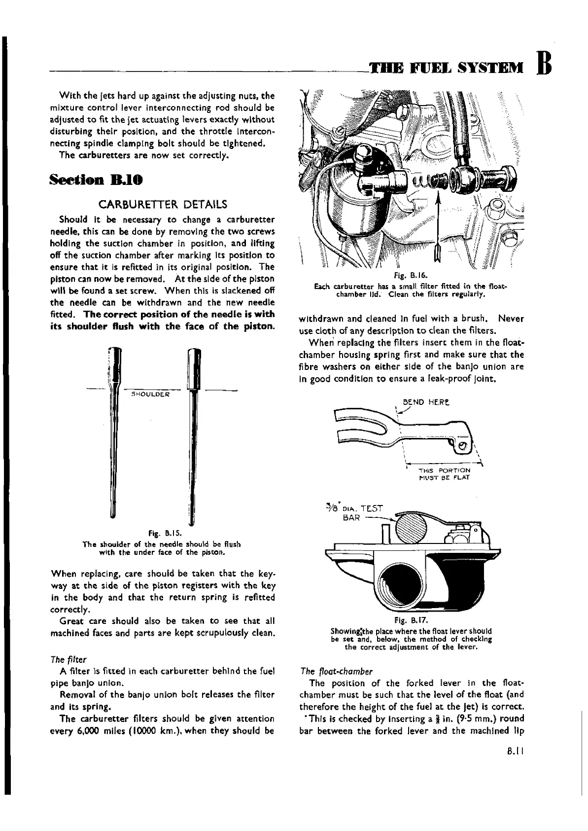
Fig. B.17.
Showing:t!le place
where
the
float lever should
be
set
and, below.
the
method
of checking
the
correct
adjustment of
the
lever.
The
~oat-chamber
The position of
the
forked lever in
the
float-
cham
ber
must
be such
that
the
level of
the
float (and
therefore
the
height of
the
fuel at
the
Jet) is
correct.
"Thls is checked by inserting a i in. (9·5 rnm.) round
bar
between
the
forked
lever
and
the
machined lip
B.I I
Wishvilles Classic
Automobile Library