A
THE
ENGINE
--
-------
-_._-
Adjust
No.
I
rocker
with
No.8
valve wide
open
tl
3
_..
., .. 6
u 5 U
.1
4
'I.'
It
,,2
u •• '''' 7
,~
u
..
tit
U 8
II
~J
I
~J
I'
It
U
tt
6 n u 3 H t, ,t
tJ
t, 4 ,.
tt
,t 5
,~
tt tt
U U
7"
~.
u 2 u
.~
u
Provision for adjusting
the
valve clearance Is made
In
the
rocker-arm by an adjustable screw and locknut.
The
tappet
adjusting screw is released by slackening
off
the
hexagon locknut
with
a spanner, while holding
the
screw against
rotation
with
a screwdriver.
~~~
Fig. A.20.
The method of settIng
the
tappets.
When
the
locknut Is released
the
valve clearance can
be
set
by
rotating
the
adjusting
screw
with
the
screw-
driver
and setting
the
clearance, by means of a feeler
gauge. to ·019 in.
(,48 mm.) as indicated In
the
Inset.
The valve clearance can
then
be set by
rotating
the
screw carefully while checking
the
clearance with a
feeler gauge at
the
valve
stem.
The
tappet
screw is
then
relocked by
tightening
the
hexagon locknut, again holding
the
tappet
screw
against
rotatlon
with
the
screwdriver. Test
the
clearance again to
ensure
it
has
not
changed.
Section
1\.28
REMOVING
AND
GRINDING THE
VALVES
The valve springs are
secured
by cups and split
conical
cotters.
In
order
to
remove a valve
the
head
must
be removed as indicated in Section A.9. placed
face downwards on
the
bench
with
a block of wood
filling
the
combustion space so
that
the
valve head is
resting on it. If
the
spring is
then
depressed.
the
collets are exposed and may be removed,
together
with
the
valve springs. On
the
valve stem
there
is a small
synthetlc
rubber
011
seal which slips off easily. A wood
A.18
block
with
packing pieces
for
each combustion
chamber
and a bench-type spring
compressor
greatly facilitate
th e car rying
out
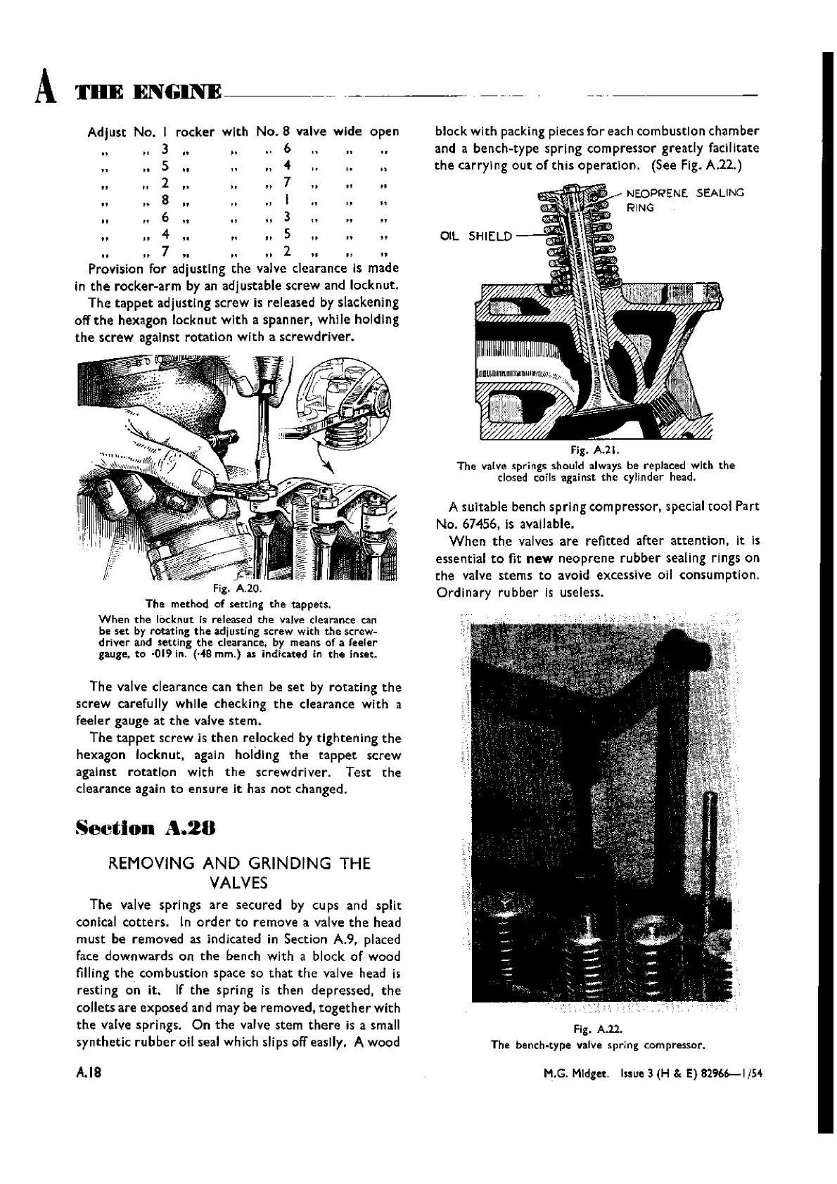
of th is 0 peration. (See Fig. A.22.)
Fig. A.21.
The valve springs should always be replaced with
the
closed coils against
the
cyli.nder head.
A suitable bench spring com pressor, special tool Part
No. 67456, Is available.
When
the
valves
are
refitted after
attention,
it is
essential
to
fit
new
neoprene
rubber
sealing rings on
the
valve stems
to
avoid excessive oil consumption.
Ordi
nary ru
bber
is useless.
Fig. A.22.
The bench-type
valve spring compressor.
M.G. MIdget. Issue 3 (H & E)
82966--1154
Wishvilles Classic
Automobile Library