A
THE
ENGINE---------
Section
1\..31
REMOVAL
AND
REPLACEMENT OF
ENGINE
AND
GEARBOX
Drain
the
cooling system
through
the
radiator and
cylinder block taps,
Remove
the
bonnet
and
radiator
(see Section
0.2).
Disconnect
the
battery
earth
lead.
Detach
the
fuel line at
the
fuel pump.
Uncouple
the
high-tension lead from
the
coil and
remove
the
low-tension
wirefrom
the
distributor
body.
Disconnect
the
mixture
control Inner and
outer
cables at
the
rear
carburetter
attachments.
Disconnect
the
throttle
ball [oint at
the
forward
end of
the
accelerator pedal arm.
Detach
the
accelerator control spring and release
the
starter
cable from
the
starter
terminal.
Remove
the
three
brass nuts holding
the
exhaust
pipe
to
the
manifold and undo
the
clip holding
the
exhaust pipe
to
the
gearbox. This
wJ1l
allow
the
front
ofthe
exhaust pipe
to
drop
clear of
the
manifold.
I
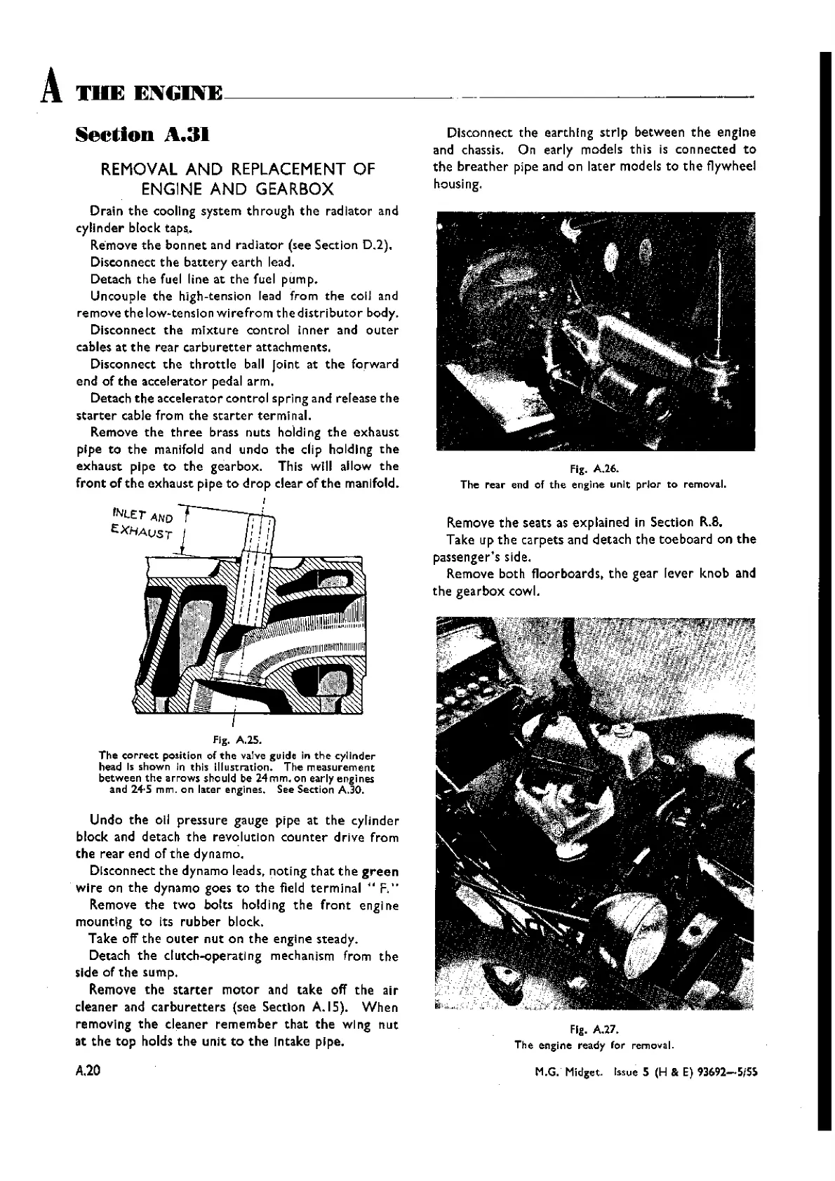
fJg. A.lS.
The
correct
position of
the
valve guide in
the
cylinder
head
Is shown in this illustration. The
measurement
between
the
arrows
should be 24 rnm, on early engJnes
and
24·5 mm. on later engines. See Section A.30.
Undo
the
011
pressure gauge pipe at
the
cylinder
block and detach
the
revolution
counter
drive from
the
rear
end of
the
dynamo.
Disconnect
the
dynamo leads, noting
that
the
green
wire on
the
dynamo goes
to
the
field
terminal"
F."
Remove
the
two
bolts holdl ng
the
front
engl ne
mountIng
to
its
rubber
block.
Take off
the
outer
nut
on
the
engine steady.
Detach
the
c1utch-operatlng mechanism from
the
side of
the
sump.
Remove
the
starter
motor
and
take
off
the
air
cleaner and
carburetters
(see Section A.IS).
When
removing
the
cleaner
remember
that
the
wing
nut
at
the
top
holds
the
unit
to
the
Intake pipe.
A.20
Disconnect
the
earthing
strip
between
the
engine
and chassis. On early models this is connected
to
the
breather
pipe and on
later
models
to
the
flywheel
housing.
fig. A.26.
The
rear
end of
the
engine
unit
prIor to removal.
Remove
the
seats as explained in Section
R.B.
Take up
the
carpets and detach
the
toe
board on
the
passenger's side.
Remove both floorboards.
the
gear
lever knob and
the
gearbox
cowl.
Fig. A.27.
The engine ready for removal.
M.G. Midget. Issue S (H & E) 93692-SISS
Wishvilles Classic
Automobile Library