E
TIlE
FLYWHEEL
AND
fJLUT£;H-
Section
Eel
RUNNING
ADJUSTMENTS
The only
adjustment
necessary
throughout
the
Jjfe
of
the
driven plate facings is
to
restore
periodically
the
free
movement
of
the
dutch
pedal (t.e,
movement
of
the
pedal before
the
release bearing comes Into
contact
with
the
release lever plate and commences
to
withdraw
the
dutch).
As
the
driven plate facings
wear.
the
free
movement
of
the
pedal will gradually
decrease, eventually preventing
the
clutch fully
~_·~u
ADJUSTING
NZ
\
LOCKNUT
'Mil'
"!!
:'1'
::1:1:&:)1
,:!,!, 1,1
W::':!l'lWW
M
p MhW
»ll
lli
ȴ
#
fall
ure.
There
should be approximately Ii in.
or
29 mm
clearance
at"
H ..
between
the
stop
nut"
C"
and
the
abutment
bracket"
0 " when
the
pedal is lightly held
with
the
carbon block In
contact
with
the
thrust
ring
by pushing lightly on
the
clutch pedal by hand. To
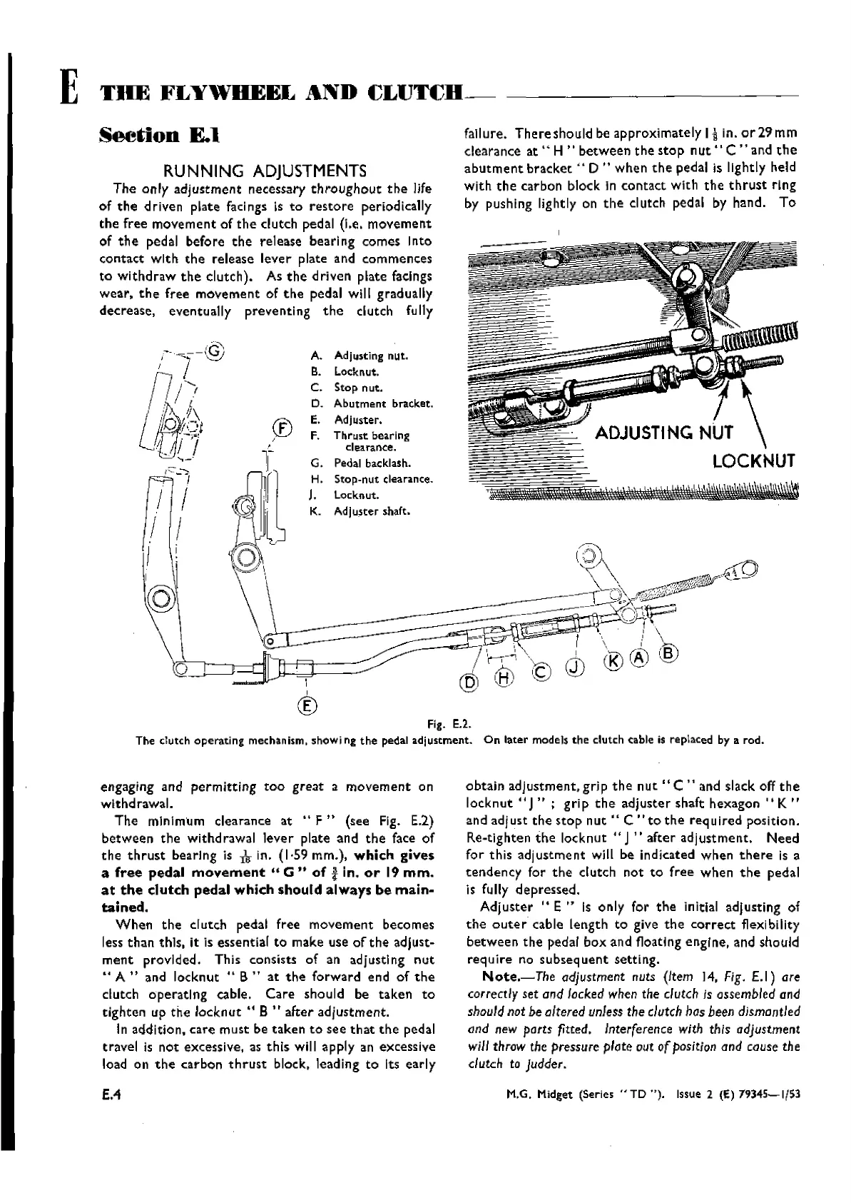
A. Adju$ting nut.
B. Locknut.
C.
Stop
nut.
D.
Abutment
bracket.
E. Adjuster,
F. Thrll$t bearing
clearance.
G. Pedal backlash.
H.
Stop-nut
clearance.
J.
locknut.
K.
Adjuster
shatt,
i
I
®
®
I
Fig. E.2.
The
dutch
operating
mechanism, showi ng
the
pedal
adjustment.
On
later
models
the
clutch cable is replaced by a rod.
engaging and
permitting
too
great
a
movement
on
withdrawal.
The
minimum clearance at ..
F"
(see Fig.
E.2)
between
the
withdrawal lever plate and
the
face of
the
thrust
bearIng is
kin.
(1·59 mm.),
which
gives
a
free
pedal
movement
..
G"
of!
in.
or
19
mm.
at
the
clutch
pedal
which
should
always
be
main-
tained.
When
the
clutch pedal free movement becomes
less
than
this, it is essential
to
make use
of
the
adjust-
ment
provided. This consists of an adjusting
nut
.. A " and locknut ..
B"
at
the
forward end of
the
clutch
operating
cable.
Care
should be taken
to
tighten up
the
locknut"
B " after adjustment.
In addition, care must be taken
to
see
that
the
pedal
travel
is
not
excessive, as this will apply an excessive
load on
the
carbon
thrust
block. leading
to
Its early
obtain
adjustment, gri p
the
nut
" C " and slack off
the
locknut"
J.. ; gri p
the
adjuster shaft
hexagon"
K ..
and ad]
ust
the
stop
nut"
C ..
to
the
req uired position.
Re-tighten
the
locknut " J" after adjustment.
Need
for this
adjustment
w1l1
be indicated when
there
is a
tendency
for
the
dutch
not
to
free
when
the
pedal
is fully depressed.
Adjuster
"E"
Is only for
the
initial adjusting of
the
outer
cable length
to
give
the
correct
flexibility
between
the
pedal box and floating engine. and should
req uire no subseq
uent
setti
ng.
Note.-The
adjustment nuts (Item 14,
Fig.
E.l)
are
correctly set and locked when the clutch is assembled
and
shouldnot be altered unless the clutch has been dismantled
ond new parts
fitted. Interference with this adjustment
will throw the
pressure plate out ofposition and couse the
dutch
to
Judder.
£.4
M.G. Midget (Series
"TD
").
Issue 2 (E) 79345-1/53
Wishvilles Classic
Automobile Library