C
TIlE
IGNITION
EQUIPMENT-------------
Section
C.8
IGNITION TIMING
ADJUSTMENT
AND
REPLACEMENT OF THE DISTRIBUTOR
When
the
distributor
has
been
removed,
it
must
be,
retimed
on
replacement.
It
should
be
set
with
points
just
breaking
at
T.D.C.
To do
this
proceed
as
follows:-
Set
the
engine
with
the
Nos.
I and 4
cylinders
on
top
dead
centre
(see
Fig. C.13).
Examine
the
valves
to
see
which
of
the
previously
mentioned
cyl
inders
is
starting
its firing
stroke.
Turn
the
distributor
until
the
rotor
Is facing
the
appropriate
segment
(I.e.
the
segment
connected
to
the
high-tension
cable
leading
to
the
same
cylinder),
and
Insert
the
distributor
in Its housi
ng,
"feeling"
it in so
that
the
nearest
tooth
is
engaged.
Turn
the
body
about
until
the
locking
screw
will
enter,
and
Jock
it.
Set
the
contact
points
to
·012 in. (-3
mm.)
(see
Sect
ion C.14), and
chec
k
th
at
the
hoie in
th
e cran kshaft
pulley
still coincides
with
the
arrow
on
the
timing
cover.
The
contact
breaker
points
should
now
just
be
commencing
to
open.
Should
this
not
be
the
case,
release
the
clamping
bolt
or
cotter
bolt
at
the
base
of
the
distributor,
turn
the
distributor
anti-clockwise
until
the
points
are
fully
closed.
and
then
turn
care-
fullyelockwlse
until
the
contact
poi nts
just
commence
to
open.
Securely
tighten
the
clamp
bolt
on
earlier
models
or
the
cotter
bolt
on
the
later
models.
Re-check
timing
to
make
sure
that
tightening
the
clamp
bolt
or
cotter
bolt
has
not
altered
the
setting.
C.8
Note.-Before
setting the timing, make sure that the
automatic advance and retard mechanism
is working
properly and
is in its (ully retarded
position
while the
timjng
is being set.
Irnportant.-
To
obtain
an
accurate
setting
an
electrical
method
should
be used
to
determine
the
actual
position
at
which
the
points
break,
and
the
following
method
can be used
:-
With
the
low-tension
lead
connected
to
the
distributor,
turn
on
the
Ignition
switch
and
connect
a 12-volt lamp in parallel
with
the
contact
breaker
...
,,'
d!1t
Urll)!
Irllll!'!JJJtI;l~dIPJII"r·IJ
d
II
.""1)\1,11\1,')1\".,(1,1111'111".,.1.101"
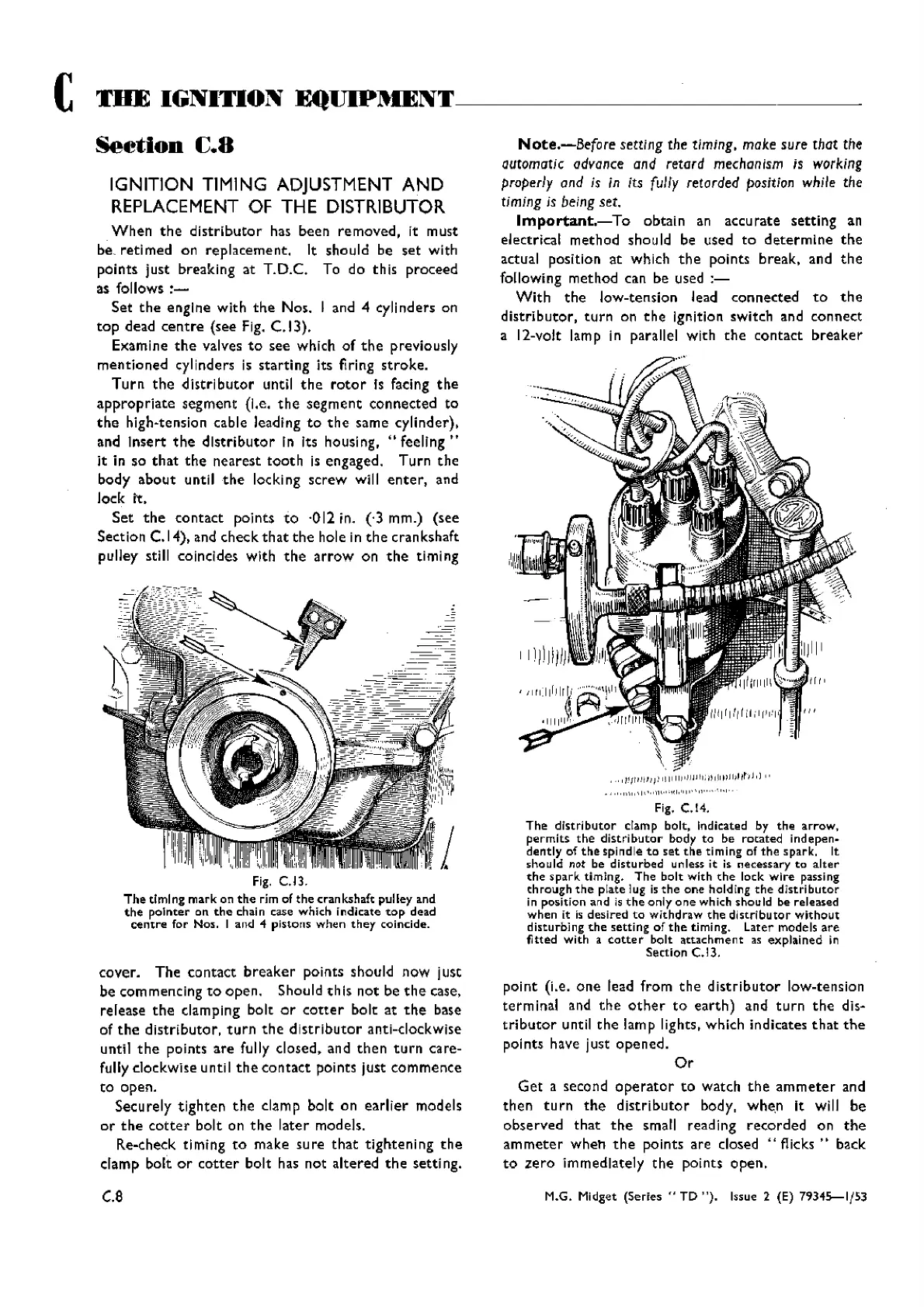
Fig. C.14.
The
distributor
clamp bolt, Indicated by
the
arrow,
permits
the
distri
butor
body to be
rotated
ind
epen-
dently
of
the
spindIe
to
set
the
ti ming of
the
s park. It
sho uId
Mt
be dlstu rbed unless it is necessary
to
alter
the
spark
timing.
The
bolt
with
the
lock
wire
passing
ehrough
the
plate Iug is
the
one
hold Ing
the
dIstri
butor
in position and is
the
oniy
one
which should be released
when
it is
desired
to
withdraw
the
distributor
without
disturbing
the
setting
of
the
timing.
Later
models
are
fitted
with
a
cotter
bolt
attachment
as
explained
in
Section C.13.
point
(i.e.
one
lead
from
the
distributor
low-tension
terminal
and
the
other
to
earth)
and
turn
the
dls-
tributor
until
the
lam
plights,
which
indicates
that
the
poi
nts
have jusc
opened.
Or
Get
a
second
operator
to
watch
the
ammeter
and
then
turn
the
distributor
body,
when
It will
be
observed
that
the
small
reading
recorded
on
the
ammeter
wheh
the
points
are
closed
"flicks"
back
to
zero
immediately
the
points
open.
M.G. Midget
(Series"
TD
").
Issue 2 (E)
79345-1/53
Wishvilles Classic
Automobile Library