FITTING
NEW
DISTRIBUTOR
BUSHES
Section
C.IO
CONDENSER
;1
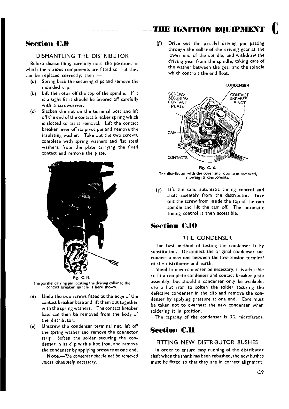
0 l'ITACT
BRE:.AKER
~~.
PIVOT
Drive
out
the
parallel
driving
pin passing
through
the
collar
of
the
driving
gear
at
the
lower
end
of
the
spindle,
and
Withdraw
the
driVing
gear
from
the
spindle,
taking
care
of
the
washer
between
the
gear
and
the
spindle
wh ich
controls
the
end
float.
SCRE'NS
SECURING
CONTACT
PLATE
l
THE
IGNITION
EqUIP~IENT
C
<n
Fig. C.16.
The distributor with the cover and rotor arm removed,
showingits components.
(g)
lift
the
cam.
automatic
timing
control
and
shaft
assembly
from
the
distributor.
Take
out
the
screw
from
inside
the
top
of
the
cam
spindle
and lift.
the
cam off.
The
automatic
timing
control
is
then
accessible.
In
order
to
ensure
easy
running
of
the
distributor
shaftwhentheshank
has
been
rebushed,
the
new
bushes
must
be
fitted
so
that
they
are
in
correct
alignment.
THE CONDENSER
The
best
method
of
testing
the
condenser
is by
substitution.
Disconnect
the
original
condenser
and
connect
a
new
one
between
the
low-tension
terminal
of
the
distributor
and
earth.
Should
a
new
condenser
be necessary, it Is advisable
to
fit a
complete
condenser
and
contact
breaker
plate
assembly,
but
should
a
condenser
only
be available,
use a
hot
iron
to
soften
the
solder
securing
the
defective
condenser
in
the
dip
and
remove
the
con-
denser
by applying
pressure
at
one
end.
Care
must
be
taken
not
to
overheat
the
new
condenser
when
soldering
it in
position.
The
capacity
of
the
condenser
is
0·2
microfarads.
Seetion
C.ll
----_
..
-----
Fig.
C.IS.
The
parallel
drlvlng pin locating the drivingcollarto the
contact breaker spindIe is here shown.
(d)
Undo
the
two
screws
fitted
at
the
edge
of
the
contact
breaker
base and lift
them
out
together
with
the
spring
washers.
The
contact
breaker
base can
then
be
removed
from
the
body
of
the
distributor.
(e)
Unscrew
the
condenser
terminal
nut.
lift off
the
spring
washer
and
remove
the
connector
strip.
Soften
the
solder
securing
the
con-
denser
in its clip
with
a
hot
Iron,
and
remove
the
condenser
by applying pressu
re
at
one
end.
Note.-The
condenser
should
not be removed
unless absolutely necessary.
DISMANTLING THE DISTRIBUTOR
aefore
dismantling, carefully
note
the
positions
in
which
the
various
com
portents
are
fitted so
that
they
can be
replaced
correctly.
then
:-
(a) Sprj ng back t he sec uri ng cIi
ps
and
remove
th
e
moulded
cap.
(b) Lift
the
rotor
off
the
top
of
the
spind
Ie. If it
is
a
tight
fit it
shou
Id be
levered
off carefu lIy
with
a
screwdriver.
(c) Slacken
the
nut
on
the
terminal
post
and
lift
off
the
end
of
the
contact
breaker
spring
which
is
slotted
to
assist
removal.
Lift
the
contact
breaker
lever
off
its
pivot
pin and
remove
the
insulating
washer.
Take
out
the
two
screws.
complete
with
spring
washers
and
flat
steel
washers.
from
the
plate
carrying
the
fixed
contact
and
remove
the
plate.
Seetion
fj.9
C.9
Wishvilles Classic
Automobile Library