==
i
t
l
I
~~_.
i/~Y
"~-{
\'_.-
-I
-~~~~~;
2.
...
tttill
111
1
11"""""""''''''''''''''''''
111.1
"
111
18
~
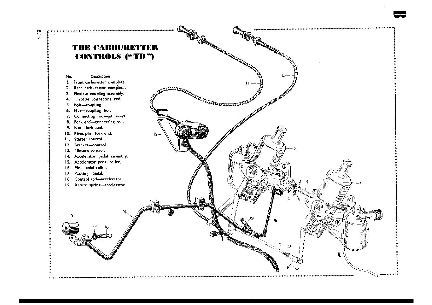
No. Description
l. Front
carburetter
complete.
2. Rear
carburetter
complete.
3. Flexible coupling assembly.
4.
Throttle
connecting rod.
5.
Bolt-coupllng.
6.
Nut-eoupllng
bolt.
7. Connecting
rod-jet
levers.
8. Fork end---<:;onnecting rod.
9.
Nut-fork
end.
10. Pivot
pin-fork
end.
II.
Starter
control.
12.
Bracket---<:;ontrol.
13. Mixture control.
14.
Accelerator pedal assembly.
15. Accelerator pedal roller.
16.
Pin-pedal
roller.
17. Packing-pedal.
18. Control
rod-accelerator.
19. Return
spring-accelerator.
<~
II
""~
I
L
'
~:::.zJ
J~lr
/1
""""~Ii
,
"'
-''''''''
",,-
/'
,
.....
"."",.,.,
............
"".,
, 8 "10
1 _
_.
J
__
'_11_'",
....,..,..,
O<t
...
,
.....
,
HII_'~'
"'-+''''~l
10<''''_'
~,
•
....-
--_
.....
'
...
11-'
j'"
'"''''''''
"""
""",,"'"''''''''''''''''''''
"""
,,".
'"
",,"
TilE
~ABnURETTER
~ONTROLS
."TD")
?'
."..
Wishvilles Classic
Automobile Library