A
TllEENGINE----------------
approximately
·020 In.
to
·025 In. ('51 mm.
to
·63 mm.).
(See Figs. A.S and A.6.)
Renew
worn
parts
as necessary.
The
pump
housing
and driven
gear
are
fitted
with
renewable
bushes.
The
oil
pump
Isassembled and replaced on
the
engine
In
the
reverse
manner
to
that
detailed for dismantling
and
removal.
Care
should be
taken
to
see
that
the
abutting
faces of
the
cylinder
block and
the
pump
are
dean
before replacing, and
that
the
paper
gasket
between
these
[olnts
is in good
condition.
If
there
Is any
doubt
as
to
its
condition,
replace It
with
a.
new
one.
No
gasket
Is fitted
between
the
pump
body
and
the
pump
cover.
colls 13t, giVing a load
of7
lb. (3·17 kilograms)
when
compressed
to
1·063 in. (27 mm.).
It is
not
adjustable and should be dismantled only
for cleaning and
examination.
The
parts
are
dls-
mantled by unscrewing
the
retaining plug In
the
bottom
side of
the
oil
pump
coverwhich
permits
their
withdrawal
from
the
pump
cover.
Care
should be
exercised
when replacIng
the
parts
of
the
relief valve
that
the
seating sleeve, ball, gulde,
spring
and fibre
washer
for
the
plug
are
correctly
replaced, and
the
fibre
washer
Is in good
condition.
If
there
is any
doubt
as
to
its
condition,
replace
it
with
a new one.
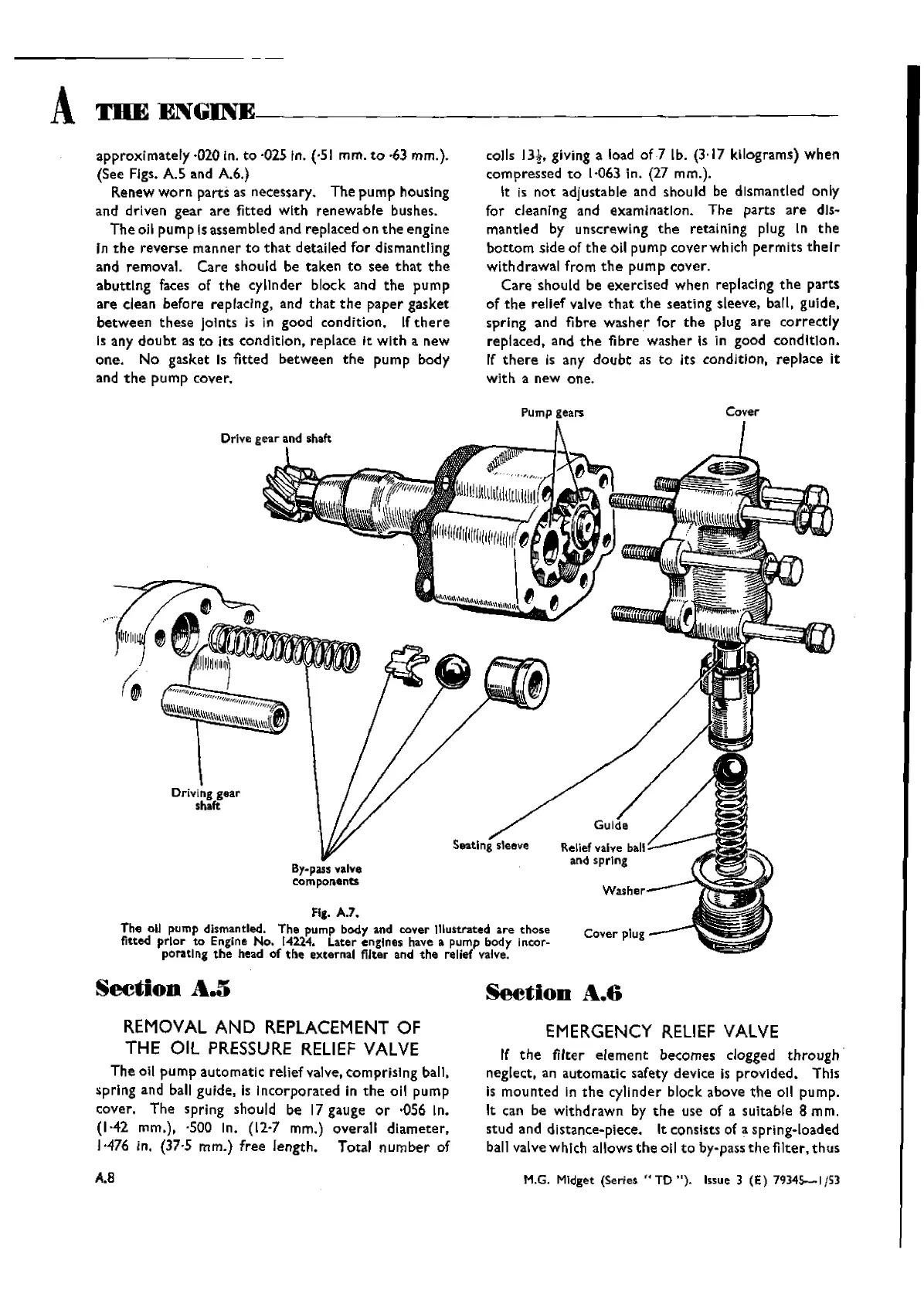
Pump gears
Cover
DrIve
gear and shaft
Driving gear
shaft
Seating
sleeve
By-pass valve
components
Fig. A.7.
The oU pump dismantled. The pump body and cover 11iustrated are those
fitted
prior
to
Engine No. [4224. Later engInes have a pump body incor-
poratlJlg
the
head
of
the
external filter and
the
relief valve.
Reliefvalve ball
and sprIng
Seetion
A.5
REMOVAL
AND
REPLACEMENT
OF
THE
Oil
PRESSURE
RELIEF
VALVE
The
all
pump
automatic
relief valve, comprisIng ball,
sprlng
and ball guide, is
incorporated
in
the
oil
pump
cover.
The
spring should be 17 gauge
or
·056 In.
(1-42
mm.), ·500 In. (12,7 mm.) overall
diameter,
1-476
in. (37,5 mm.)
free
length.
Total
number
of
A.a
Seetion
A.6
EMERGENCY
RELIEF
VALVE
If
the
filter
element
becomes clogged
through
neglect, an
automatic
safety device Is
prcvlded,
This
is
mounted
In
the
cylinder
block above
the
all pump.
It can be
withdrawn
by
the
use of a suitable 8 mm.
stud
and distance-piece. It consists of a spring-loaded
ball valve which allows
the
oil
to
by-pass
the
filter,
thus
M.G. MIdget
(Series"
TO
").
Issue 3 (E)
79345-1/53
Wishvilles Classic
Automobile Library