----~--------THE
IGNITION EQUIPMENT C
and a good
earthing
pelnt,
No reading
lndl-
cates a damaged cable
or
loose connections.
(d) Starter switch
to ammeter
(brown
lead). Con-
nect a
voltmeter
to
ammeter
terminal
and
earth.
No reading Indicates faulty cable
or
loose connections.
(e) Ammeter.
Connect
voltmeter
to
other
am-
meter
terminal
and
earth.
No reading lndl-
cates fault In am
meter.
which must be renewed.
(n
Ammeter to
control
box terminal" A ..
(brown
with
white
lead).
Connect
voltmeter
to
control
box
terminal
"A"
and
earth.
No
reading Indicates faulty cable
or
loose con-
nections.
(g)
Control
bOK terminal
"A
L"
Con
neet
volt-
meter
to
control
box
terminal
.. AI " and
earth.
No reading Indicates fault in
series
winding of
control
box.
(h)
Control
box terminal
"A
I .. to
lighting
and
ignition switch terminal
"A"
(brown
with
blue lead).
Connect
voltmeter
to
.. A "
terminal on switch and
earth.
No
reading
indicates faulty cable
or
loose connections.
(j)
Lighting
and
ignition
switch terminal
"IG."
Connect
voltmeter
to
"IG"
terminal
on
switch and
earth.
No reading indicates
fault In switch, which
must
be
renewed.
(k) ..
IG
.. terminal to
control
box terminal " A3 "
(white
lead).
Connect
voltmeter
to
"A3
"
terminal
on
control
box
and
earth.
No
reading indicates faulty cable
or
loose con-
nections.
(I)
Control
box terminal .,
A3"
to
fgn/tion
coil
terminal"
SW
..
(wnite
lead).
Connect
a volt-
meter
to
the
ignition coil
terminal
..
SW
"
and
to
earth,
No reading indicates a damaged
cable
or
loose connections.
(m) Ignition coi/. Disconnect
the
cable from
the
" CB "
terminal
of
the
ignition coil and con-
nect
a
voltmeter
to
this terminal and
to
earth.
No reading Indicates a fault in
the
primary
wInding of
the
coil and a
replacement
coil
must
be fitted. If
the
correct
reading Is
given,
remake
the
connection
to
the
coil
terminal.
(n) Ignition coli to distributor (white
with
black
lead). Disconnect
the
cable from
the
low-
tension
terminal
on
the
distributor
and
connect
the
voltmeter
to
the
end
of
this
cable and
to
earth.
No reading indicates a
damaged cable
or
loose connections.
(0)
Contact
breaker
Gnd
condenser.
Connect
the
voltmeter
across
the
contact
breaker
points.
No reading Indicates a fault in
the
condenser.
Seetion
C.3
HIGH-TENSION
CABLES
(0)
The
high-tension cables must be examined
carefully and any which have
the
Insulation
cracked.
perished
or
da.maged in any way
must
be replaced by 7 mm. rubber-covered
Ignition cable.
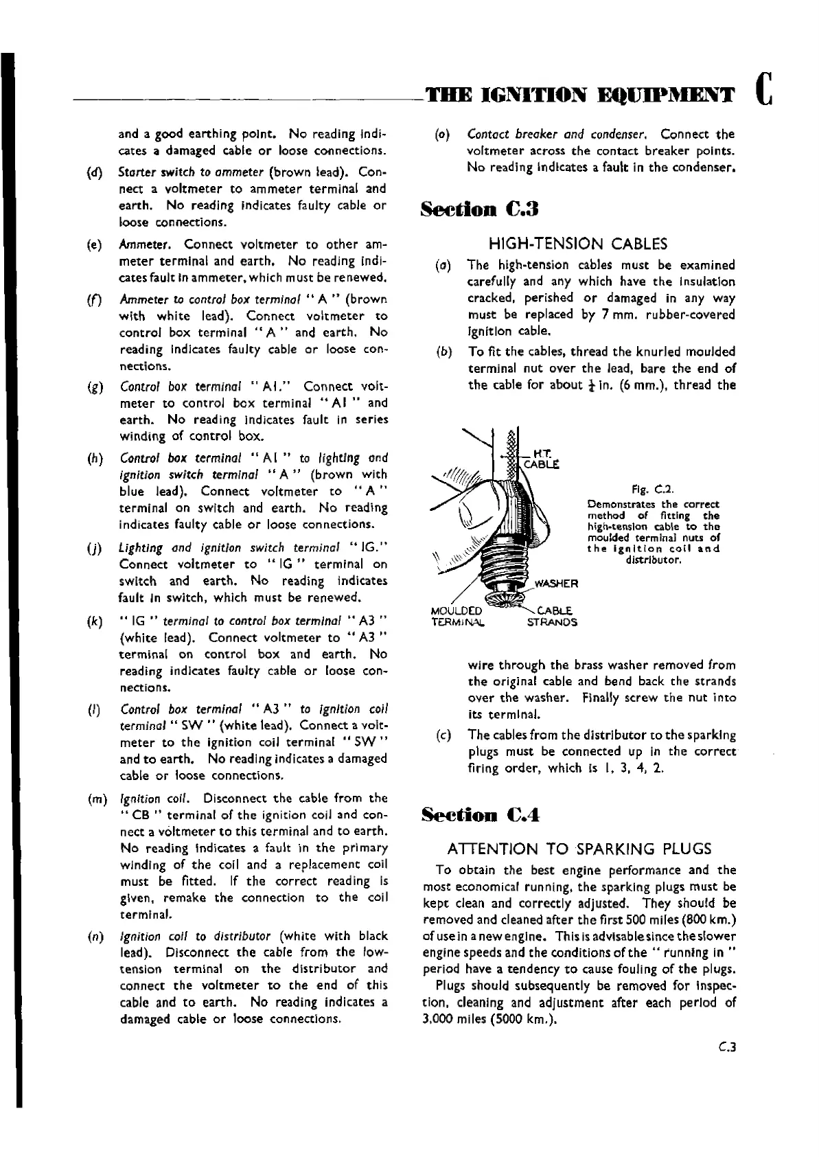
(b) To fit
the
cables,
thread
the
knurled
moulded
terminal
nut
over
the
lead, bare
the
end
of
the
cable for
about
tin.
(6mm.),
thread
the
Fig. C.2.
Demonstrates
the
correct
method
of fitting
the
high-tension
cable
to
the
moulded terminal nuts
of
the
ignition
coil
and
dIstrlbut0 r.
MOULDED
T£RMlNA!.
wire
through
the
brass
washer
removed from
the
original cable and bend back
the
strands
over
the
washer. Finally screw
the
nut
into
its
terrnlnal,
(c)
The
cables from
the
distrIbutor
to
the
sparking
plugs must be
connected
up in
the
correct
firing
order,
whlch Is I. 3. 4, 2.
SeetiOD
£.4
ATTENTION TO SPARKING
PLUGS
To
obtain
the
best
engine
performance and
the
most economical running.
the
sparking plugs
must
be
kept
clean and
correctly
adjusted.
They
should be
removed and cleaned
after
the
first 500 miles (800 km.)
of use in
a
new
engIne. This isadvisablesince
the
slower
engine speeds and
the
conditions of
the
.. running in ..
period have a
tendency
to
cause fouJing
of
the
plugs.
Plugs should
subsequently
be removed for inspec-
tion, cleaning and
adjustment
after each perlod of
3,000 miles
(SOOO
km.),
C.3
Wishvilles Classic
Automobile Library