SeedOD
.&.38
THE
ENGINE
MOUNTING
AND
CONTROL LINK
The
power
unit
is flexibly
mounted
to
the
chassis
frame
on
a ru
bber
block
at
the
front
and on
two
ru
bber
blocks
underneath
the
gearbox
at
the
rear.
As
the
location
of
these
rubber
mountings
would
permit
a
large
rockJng
movement
of
the
power
unit
under
certain
circumstances, a
control
link Is fitted
at
the
forward
end
to
control
the
torque
reaction effects on
the
power
unit.
The
rear
mounting
consists
of
two
loose
rubber
blocks on which
the
engine
rests
and which
are
TIIti
ENGINE A
the
adjuster
in
the
appropriate
direction,
allowing
the
assembly
to
be removed
complete
with
Inner
rubbers
and cups by rocking
the
engine.
Refitting
the
control
link
Screw
the
adjuster
locknuts
right
home
on
the
threads
of
the
two
adjusting
rods
and
screw
the
rods
into
the
adjuster
barrel as far as
they
will go. Place
the
two
Inner
cups and
rubbers
on
the
ends
of
the
adjusting rods. I
nsert
one
end
of
the
assem bly th rough
the
bracket
on
the
engine and. holding it
with
Its
rubber
tight
against
the
bracket,
rock
the
engine
towards
the
left of
the
car
on its
rubber
mounting
to
enable
the
other
end of
the
adjusting rod assembly
to
be
entered
into
the
frame bracket.
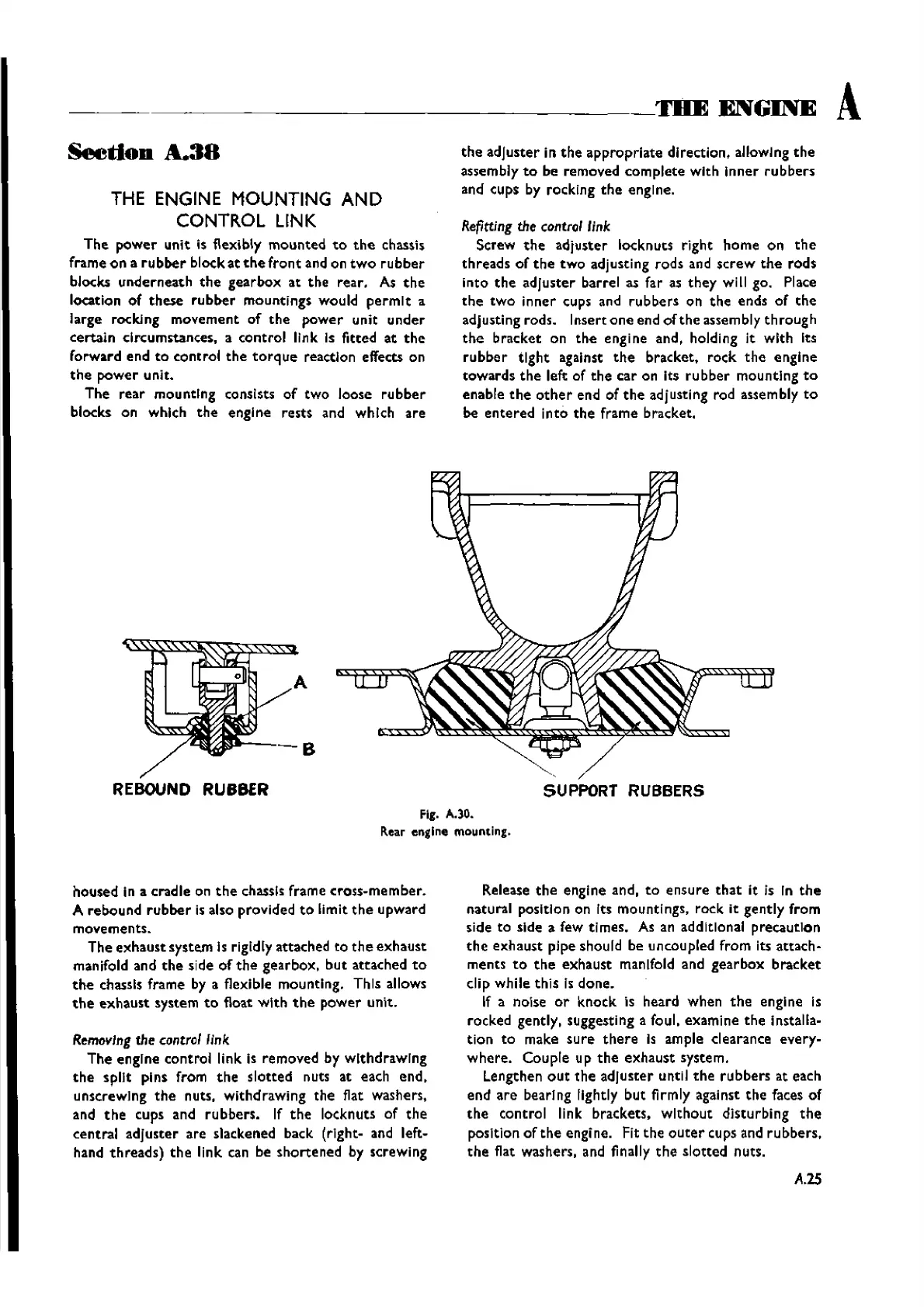
REBOUND RUBBER
SUPPORT RUBBERS
Fig. A.30.
Rear engine mounting.
housed
in a
cradle
on
the
chassis frame
cross-member.
A
rebound
rubber
is also provided
to
limit
the
upward
movements.
The
exhaust
system Is rigidly attached to
the
exhaust
manifold and
the
side
of
the
gearbox,
but
attached
to
the
chassis frame by a flexible mounting. This allows
the
exhaust
system
to
float
with
the
power
unit.
Removing
the
control
link
The
engine
control
link is
removed
by WithdrawIng
the
spilt
pins from
the
slotted
nuts at each
end,
unscrewing
the
nuts,
withdrawing
the
flat washers,
and
the
cups and
rubbers.
If
the
locknuts of
the
central
adjuster
are
slackened back (rlght- and left-
hand
threads)
the
link can be
shortened
by screwing
Release
the
engine and,
to
ensure
that
It Is In
the
natural position on Its mountings,
rock
it
gently
from
side to side a few ttrnes, As an additional
precaution
the
exhaust
pipe should be uncoupled
from
its
attach-
ments
to
the
exhaust
manifold and
gearbox
bracket
clip
while
this
Is
done.
If a noise
or
knock
is
heard
when
the
engine is
rocked gently, suggesting a foul,
examine
the
Installa-
tion
to
make
sure
there
Is ample clearance
every-
where.
Couple
up
the
exhaust
system.
Lengthen
out
the
adjuster
until
the
rubbers
at each
end
are
bearing lightly
but
firmly against
the
faces
of
the
control
link
brackets.
without
disturbing
the
position
of
the
engine. Fit
the
outer
cups and
rubbers,
the
flat washers, and finally
the
slotted
nuts.
A.25
Wishvilles Classic
Automobile Library