N ELECTRICAL
EQUIPMENT-------------
worn so
that
they
no longer bear on
the
commutator
or
if
the
brush flexible has become exposed on
the
running face they must be renewed.
If
the
commutator
is blackened
or
dirty. clean it by
holding a petrol-moistened
doth
against it while
the
armature
Is
rotated.
Dismantling
Take off
the
cover band
"A"
(Fig.
N.II)
at
the
commutator
end. hold back
the
brush
springs"
D "
and
take
out
the
brushes"
B " from
their
holders.
Withdraw
the
two
through
bolts and remove
the
armature
complete with driving end bracket.
Remove
the
terminal nuts and washers from
the
terminal post at
the
commutator
end bracket and
remove
the
commutator
end bracket.
Brushes
(0)
Test
the
brush springs with a spring scale.
The
correct
tension is 30-40 oz.
(850--1134
grams). Fit a new spring If
the
tension Is low.
(b) If
the
brushes are
worn
so
that
they
no longer
bear on
the
commutator,
or
If
the
flexible
connector
has become exposed. on
the
running
face,
they
must be renewed.
Two
of
the
brushes are connected
to
termInal eyelets
"A
It
(Fig. N.12) attached to
the
brush boxes
"
B"
on
the
commutator
end bracket. and
two
"A"
(Fig. N.13)
are
connected
to
a
tappi ng .. B " on
the
field coiIs.
The flexible connectors
must
be removed by un-
soldering and
the
connectors of
the
new brushes
secured In
their
place by soldering. The brushes are
pre-formed so
that
bedding of
theIr
working face
to
the
commutator
is unnecessary.
Drive
(0) If
the
pinion is
tight
on
the
screwed sleeve,
wash away any
dlrt
with paraffin (kerosene).
(b) If any parts
are
worn
or
damaged
they
must be
renewed.
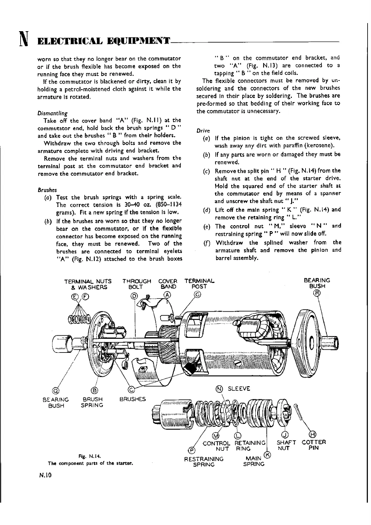
(c) Remove
the
split
pin"
H " (Fig. N.14) from
the
shaft
nut
at
the
end
of
the
starter
drive.
Hold
the
squared end of
the
starter
shaft at
the
commutator
end by means of a
spanser
and unscrew
the
shaft
nut"
J."
(d)
Lift
off
the
main spring .. K .. (Fig. N.14) and
remove
the
retaining
ring"
L."
(e) The control
nut
..
M,"
sleeve
"N"
and
restraining
spring"
P"
will now slide off.
(n
Withdraw
the
spllned
washer
from
the
armature
shaft and remove
the
pinion and
barrel assembly.
Fig. N.H.
The
component
parts of
the
$tarter.
BEARING
BUSH
R
COTTER
PIN
@ SLEEVE
\
COVER
TERMINAL
BAND POST
A G
...,.jlLL--..---....>;r'"
THROUGH
BOLT
D
C
BRUSHES
i
I
®
BRUSH
SPRING
TERMINAL NUTS
& WASHERS
E ®
BEARING
BUSH
N.IO
Wishvilles Classic
Automobile Library
 Loading...


