B
TIlE
FUEL
SYSTEM----------------
you should be able
to
blow freely
but
not
be able
to
suck air back, and with
the
latter
you should be able
to
suck freely and
not
blow
air
back. If
these
are
In
order
it Is best
to
leave
the
valves alone,
Clean
the
filter in fuel with a brush and swill
out
the
body of
the
pump.
Next
unscrew
the
diaphragm assembly from Its
trunnion
in
the
contact
breaker.
This is
done
by
rotating
the
whole assembly in an anti-clockwise
direction.
While
doing this, care should be
taken
not
to
lose
the
brass rollers fitted behind
the
dia-
phragm. The easiest method Is to hold
the
body in
the
left hand and
to
rotate
the
diaphragm.
Now
remove
the
contact
breaker
cover
by taking
off
the
nut
which holds it In place on
the
terminal,
and
then
undo
the
farther
nut
on
the
terminal. which acts
as a seating
for
the
cover. Beneath this will be found
a lead
washer
which is squeezed
into
the
thread
on
the
terminal. This should be
cut
away
with
a pocket
knife, allowing
the
terminal
to
be pushed down a
short
way so
that
the
tag on
the
coli end is free on
the
terminal.
The
5 B.A. screw holding
the
contact
blade in
position should now be removed,
together
with Its
spring
washer
and
the
contact
blade.
The
two
long 2 B.A. screws holding
the
bakelite
pedestal In place should now
be removed,
together
with
their
spring washers. This will enable
the
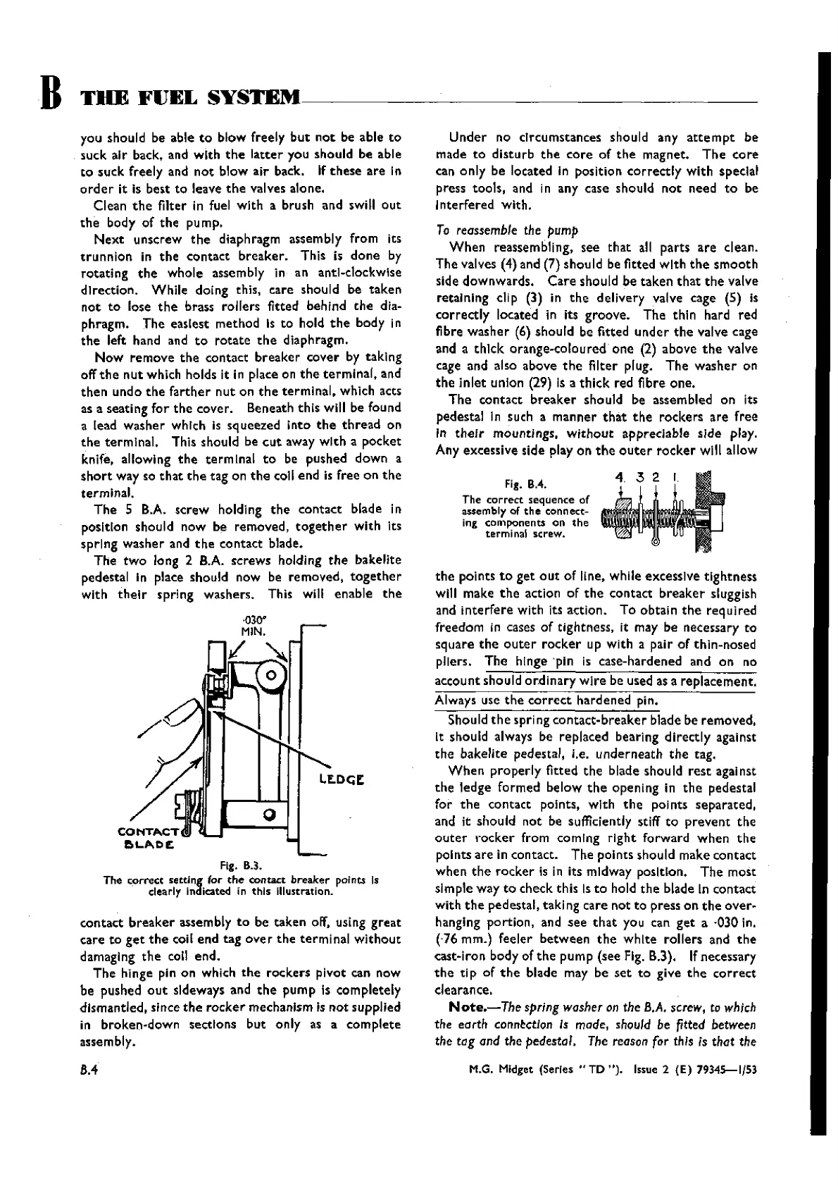
Fig. 8.3.
The
correct
setting for
the
contact
breaker
points Is
clearly
Indicated in
this
Illustration.
contact
breaker
assembly
to
be taken off, using
great
care
to
get
the
coil end tag
over
the
terminal
without
damaging
the
coli end.
The
hinge pin on which
the
rockers pivot can now
be pushed
out
sideways and
the
pump Is completely
dismantled, since
the
rocker
mechanism Is not supplied
in broken-down sections but only as a
complete
assembly.
8,4
Under
no circumstances should any
attempt
be
made
to
disturb
the
core
of
the
magnet.
The
core
can only be located in position
correctly
with special
press tools, and in any case should
not
need
to
be
Interfered with.
To
reassemble the pump
When
reassembling, see
that
all parts
are
clean.
The valves
(4) and (7) should be fitted with
the
smooth
side downwards.
Care
should be
taken
that
the
valve
retaining elip
(3) in
the
delivery valve cage (5) Is
correctly
located in its groove. The thin hard red
fibre
washer
(6)should be fitted
under
the
valve cage
and
a
thick
orange-coloured
one
(2) above
the
valve
cage and also above
the
filter plug.
The
washer
on
the
inlet
union (29) Is a
thick
red fibre one.
The
contact
breaker
should be assembled on its
pedestal In such a manner
that
the
rockers
are
free
In
their
mountings,
without
appreciable sIde play.
Any excessive side play on
the
outer
rocker
wlll allow
Fig. BA.
The
correct
sequence of
assembly of
the
connecc-
ing components on
the
terminal screw.
the
points
to
get
out
of line. while excessive tightness
will make
the
action of
the
contact
breaker
sluggish
and
interfere
with its action. To obtain
the
required
freedom
in cases of tightness, it may be necessary
to
square
the
outer
rocker
up with a pair of thin-nosed
pliers.
The
hInge ·pln Is case-hardened and on no
account should
or.dinary
wire
be used as a replacement.
Always use
the
correct
hardened pin.
Should
the
spring
contact-breaker
blade be removed,
It should always be replaced bearing directly against
the
bakelite pedestal, I.e,
underneath
the
tag.
When
properly
fitted
the
blade should
rest
against
the
ledge formed below
the
opening in
the
pedestal
for
the
contact points, with
the
points separated,
and it should
not
be sufficiently stiff
to
prevent
the
outer
rocker
from coming
right
forward
when
the
points
are
in contact. The points should make contact
when
the
rocker
is in its midway position.
The
most
simple way
to
check this Is
to
hold
the
blade In contact
with
the
pedestal, taking care not
to
press on
the
over-
hanging portion, and
see
that
you can
get
a ·030in.
(-76
mm.) feeler
between
the
white
rollers and
the
cast-iron body of
the
pump (see Fig.
B.3).
Ifnecessary
the
ti p of
the
blade may be
set
to
give
the
correct
clearance.
Note.-The
springwasheron the
B.A.
screw, to which
the earth
conn~ctlon
Is made,
should
be fitted
between
the tag and the pedestal. The
reason
for this ;s that the
M.G. Midget
(Series"
TO
").
Issue 2
(E)
79345-1/53
Wishvilles Classic
Automobile Library