B
THE
FUEL
SYSTEM-----------------
8.6
If a roller
drops
out
of position
it
will
get
trapped
between
the
two
ports, and this will
cut
a hole In
the
diaphragm.
Make
sure
th:lt
the
cast-Iron body Is seating
properly
on
the
main body, and Insert
the
five
coupling screws and
the
earth
terminal screw.
These
screws should
not
be screwed up tightly
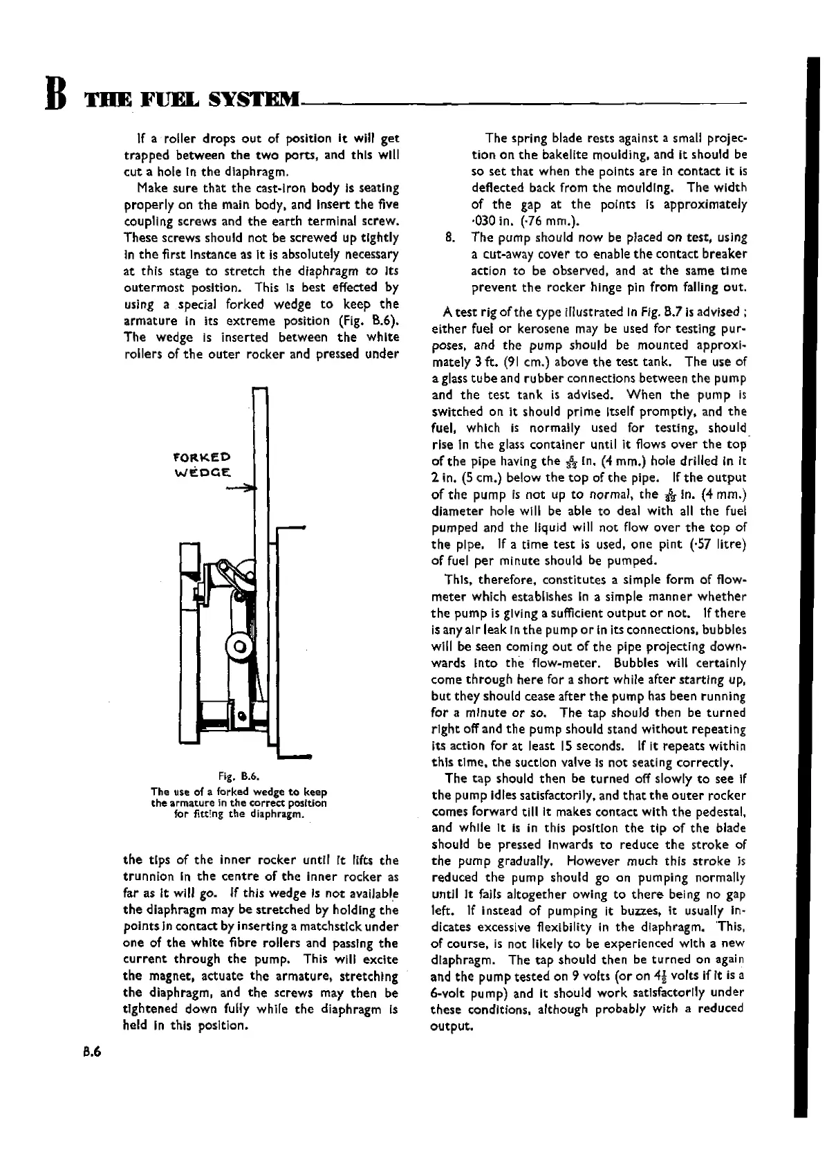
In che first Instance as It Is absolutely necessary
at this stage to
stretch
the
dIaphragm to Its
outermost
position. This Is best effected by
using a special forked wedge
to
keep
the
armature
In its
extreme
position (Fig. B.6).
The
wedge Is Inserted between
the
white
rollers of
the
outer
rocker
and pressed
under
'FORKED
WEOGE
Fig. 8.6.
The use of a forked wedge to keep
the
armature
in
the
correct
position
for fittIng
the
diaphragm.
the
tips of
the
inner
rocker
until rt lifts
the
trunnion
In
the
centre
of
the
inner
rocker
as
far as It will go. If this
wedge
Is
not
available
the
diaphragm may be
stretched
by holding
the
points In contact by inserting a matchstick
under
one
of
the
white
fibre rollers and passing
the
current
through
the
pump. This will
exclte
the
magnet,
actuate
the
armature,
stretching
the
diaphragm, and
the
screws may
then
be
tightened
down fully while
the
diaphragm Is
held In this posItIon.
The
spring blade rests against a small projec-
tion
on
the
bakelite moulding, and It should be
so
set
that
when
the
points
are
In
contact
it is
deflected back from
the
moulding.
The
width
of
the
gap at
the
points Is approximately
·030in. (,76 mrn.],
B.
The
pump should now be placed on
test,
using
a cut-away cover
to
enable
the
contact
breaker
action
to
be observed, and at
the
same
time
prevent
the
rocker
hinge pIn from falling
out.
A
test
rig of
the
type
illust rated In Fig. B.7 is advised ;
either
fuel or kerosene may be used for
testing
pur-
poses, and
the
pump
should be mounted approxl-
rnately 3 ft.
(91
em.) above
the
test
tank. The use of
a glass
tube
and
rubber
connections
between
the
pump
and
the
test
tank. is advised.
When
the
pump
Is
switched on it should prime Itself promptly, and
the
fuel, which is normally used for testing, should
rise In
the
glass
container
until it flows
over
the
top
of
the
pipe having
the
:&
In. (4 mm.) hole drilled in It
2 in. (5 crn.) below
the
top
of
the
pipe. If
the
output
of
the
pump is
not
up
to
normal,
the
"*
in. (4 mrn.)
diameter
hole will be able
to
deal with all
the
fuel
pumped and
the
liquid will
not
flow
over
the
top
of
the
pipe. If a
time
test
is used,
one
pint
(·57 litre)
of fuel
per
minute should be pumped.
This,
therefore,
constitutes a Simple form of flow-
meter
which establishes In a simple
manner
whether
the
pum
pIs
glving a sufficient
output
or
not. Ifth ere
is any alr leak In
the
pump 0 r In Its con nectlons, bubbles
will be seen coming
out
of
the
pipe projecting down-
wards Into
the
flow-meter. Bubbles will certainly
come
through
here
for a
short
while
after
starting
up,
but
they
should cease
after
the
pump has been running
for
a
minute
or
so.
The
tap
should
then
be
turned
right
off and
the
pump should stand
without
repeating
its action for at Ieast 15 seconds. If It
repeats
within
this
time.
the
suction valve Is
not
seating
correctly.
The
tap
should
then
be
turned
off slowly
to
see If
the
pump idles satisfactorily. and
that
the
outer
rocker
c.omes forward till it makes contact with
the
pedestal,
and while It
Is in this posItIon
the
tip
of
the
blade
should be pressed Inwards
to
reduce
the
stroke
of
the
pump
gradually. However much this
stroke
Is
reduced
the
pump should go on pumping normally
until It fails
altogether
owing
to
there
being no gap
left. If instead of pumping It buzzes, it usually ln-
dicates excessive flexibility in
the
diaphragm. 'This,
of course, Is not likely
to
be experienced with a new
diaphragm. The
tap
should
then
be
turned
on again
and
the
pump
tested
on 9 volts
(or
on
4!
volts if It is a
6-volt pump) and it should
work
satisfactorily
under
these
conditions, although probably with a reduced
output.
Wishvilles Classic
Automobile Library