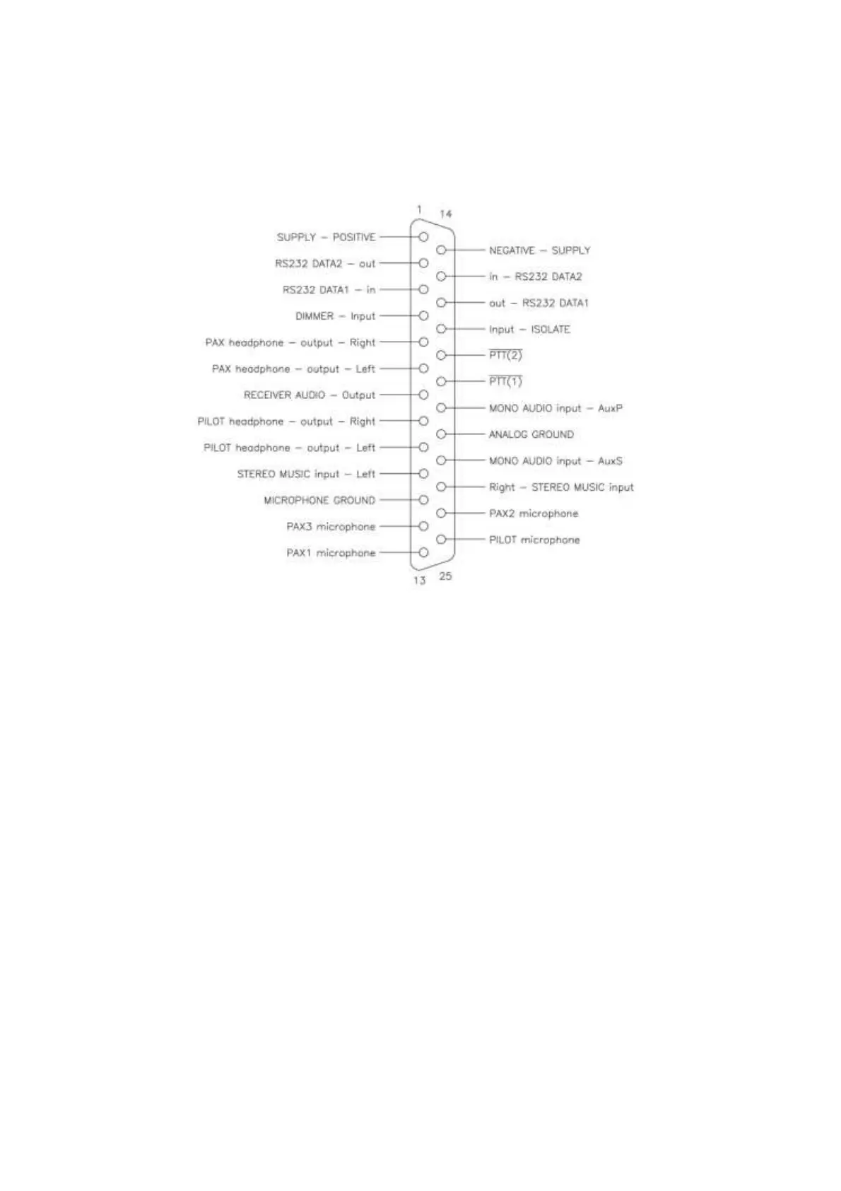
DB-25 connector pin out
A 25 pin female SubD connector on the rear panel provides all low frequency
signal and power connections to the V6 Transceiver. The wiring harness in
the aircraft requires a male DB-25 connector.
A clean DC supply of 12V or 24V nominal is required. Internal protection will
cause the Radio to be switched off if the DC voltage exceeds 32V. The
negative supply lead to the Radio should be terminated at a separate
connection point as close as possible to the negative terminal of the battery.
This will help to reduce interference from other electrically noisy equipment in
the aircraft.
A four microphone intercom circuit is provided with two stereo headphone
circuits. One microphone (the 'PILOT microphone') is intended for the pilot
and the others for passengers. It is possible to connect several microphones
in parallel at each input. In this case it is recommended that identical
headsets be used.
A stereo music input is provided. A suitable jack, such as a 3.5mm stereo
audio jack, should be provided if this input is to be used. An MP3 player may
then easily be connected. For best results, the jack should be insulated from
the airframe and its ground connected to the analog ground pin on the Radio.
Two mono auxiliary audio inputs are provided. These inputs can be used to
connect alarms, EFIS voice alerts and the like.
Two stereo headphone outputs are provided. These are capable of driving 8
ohm speakers or multiple (up to 8) standard aviation headsets. The pilot's
headset should be connected to the PILOT headphone output. The
installation may be wired for mono headsets. In this case, headphone
connections should use only one 'side' of the stereo outputs – all connected
23