to the same side. The corresponding 'side' of the stereo input can then be
used for music.
Separate analog and microphone grounds are provided. They should not be
connected to supply ground or the airframe as this may introduce audio
interference. Insulating washers or an insulating panel should be used to
mount headset and microphone jacks so that these may be connected back
to the analog and microphone grounds respectively without connecting to the
airframe. Screened cable should be used for microphone connections.
Two PTT inputs are provided. A PTT is activated by connecting the input to
power supply ground or audio ground. Airframe ground may also be
acceptable.
A Pilot Isolate input is provided. This feature may be activated by connecting
the input to power supply ground or audio ground. Airframe ground may also
be acceptable.
Two independent RS232 serial communications ports are provided. These
may be used to connect to two independent EFIS systems for full remote
control of the V6 Transceiver. These ports are equivalent and
interchangeable. A specification for the communications protocol is available
at www.MGLAvionics.co.za.
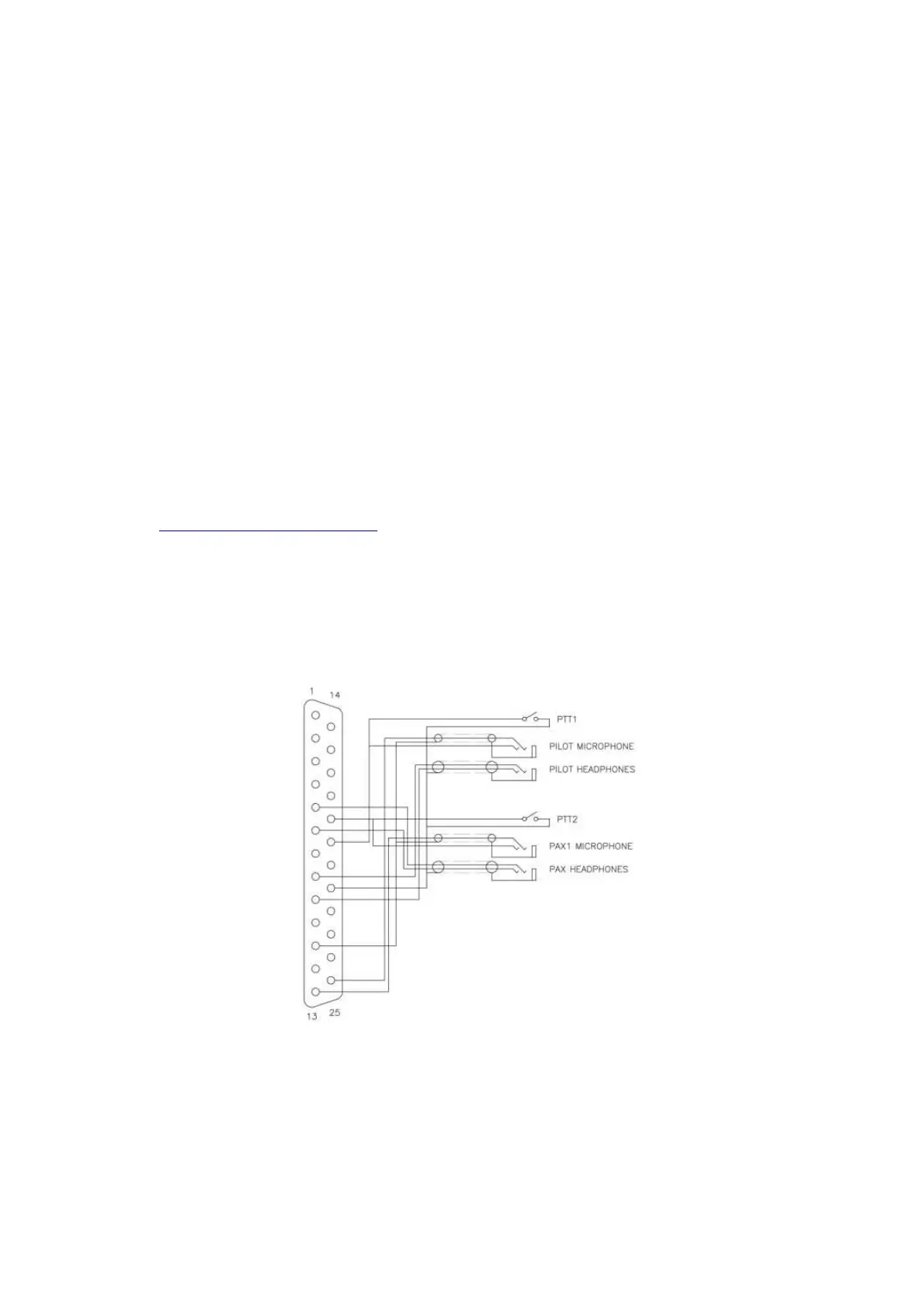
Typical wiring diagrams
Power supply wiring is not shown. A 2.5A – 5A circuit breaker or fuse must be
installed. This is mandatory. Note the use of shielded audio cable and, in
particular, the connections for the shielding of that cable.
This diagram shows a minimal two place installation with wiring for both
external PTTs and headsets that provide built in PTT buttons.
24